
Optical detection of vibrations

a vibration detection and optical detection technology, applied in the direction of subsonic/sonic/ultrasonic wave measurement, measurement devices, instruments, etc., can solve the problem of light distribution with varying intensity in spa

Active Publication Date: 2022-06-28
ELBIT SYST LAND & C4I
View PDF15 Cites 0 Cited by
  • Summary
  • Abstract
  • Description
  • Claims
  • Application Information

AI Technical Summary

Benefits of technology

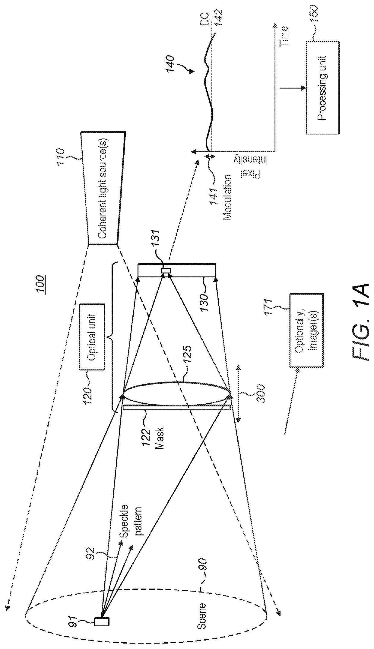
The invention is a system that uses a laser to shine light on a scene, and a special camera to capture the reflections of that light. By analyzing the intensity of the captured light, the system can create a map of the vibrations in the scene. This technology can be used to make sure that objects in a scene are not shaking or moving too much, which could cause damage or other issues.

Problems solved by technology

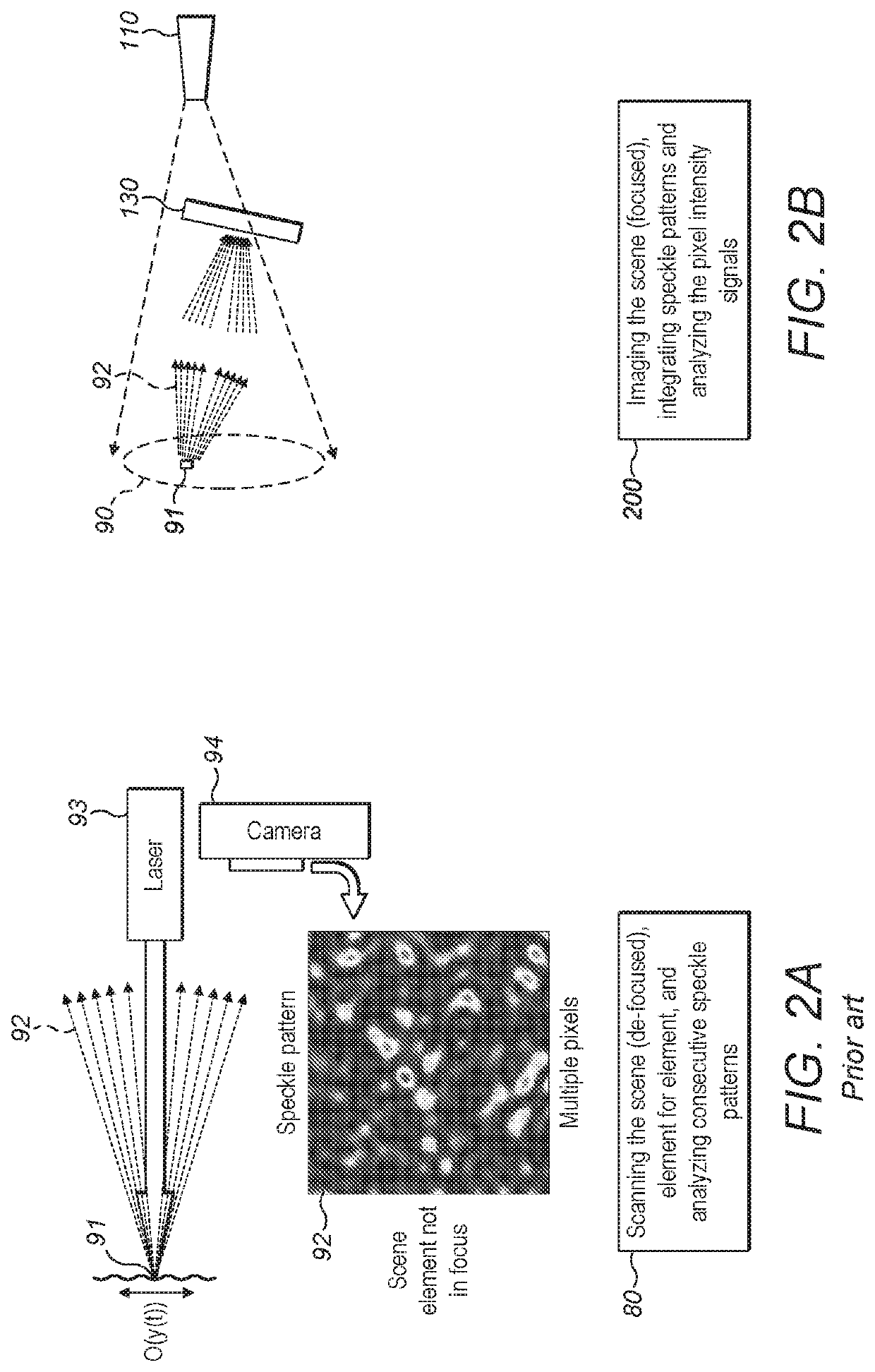
Consequently, the beam portions scattered from different surface portions interfere with each other, resulting in a light distribution with varying intensity in space.

Method used


Image

  • Optical detection of vibrations
  • Optical detection of vibrations
  • Optical detection of vibrations

Examples


Embodiment Construction

[0016]In the following description, various aspects of the present invention are described. For purposes of explanation, specific configurations and details are set forth in order to provide a thorough understanding of the present invention. However, it will also be apparent to one skilled in the art that the present invention may be practiced without the specific details presented herein. Furthermore, well known features may have been omitted or simplified in order not to obscure the present invention. With specific reference to the drawings, it is stressed that the particulars shown are by way of example and for purposes of illustrative discussion of the present invention only, and are presented in the cause of providing what is believed to be the most useful and readily understood description of the principles and conceptual aspects of the invention. In this regard, no attempt is made to show structural details of the invention in more detail than is necessary for a fundamental u...


PUM


Abstract

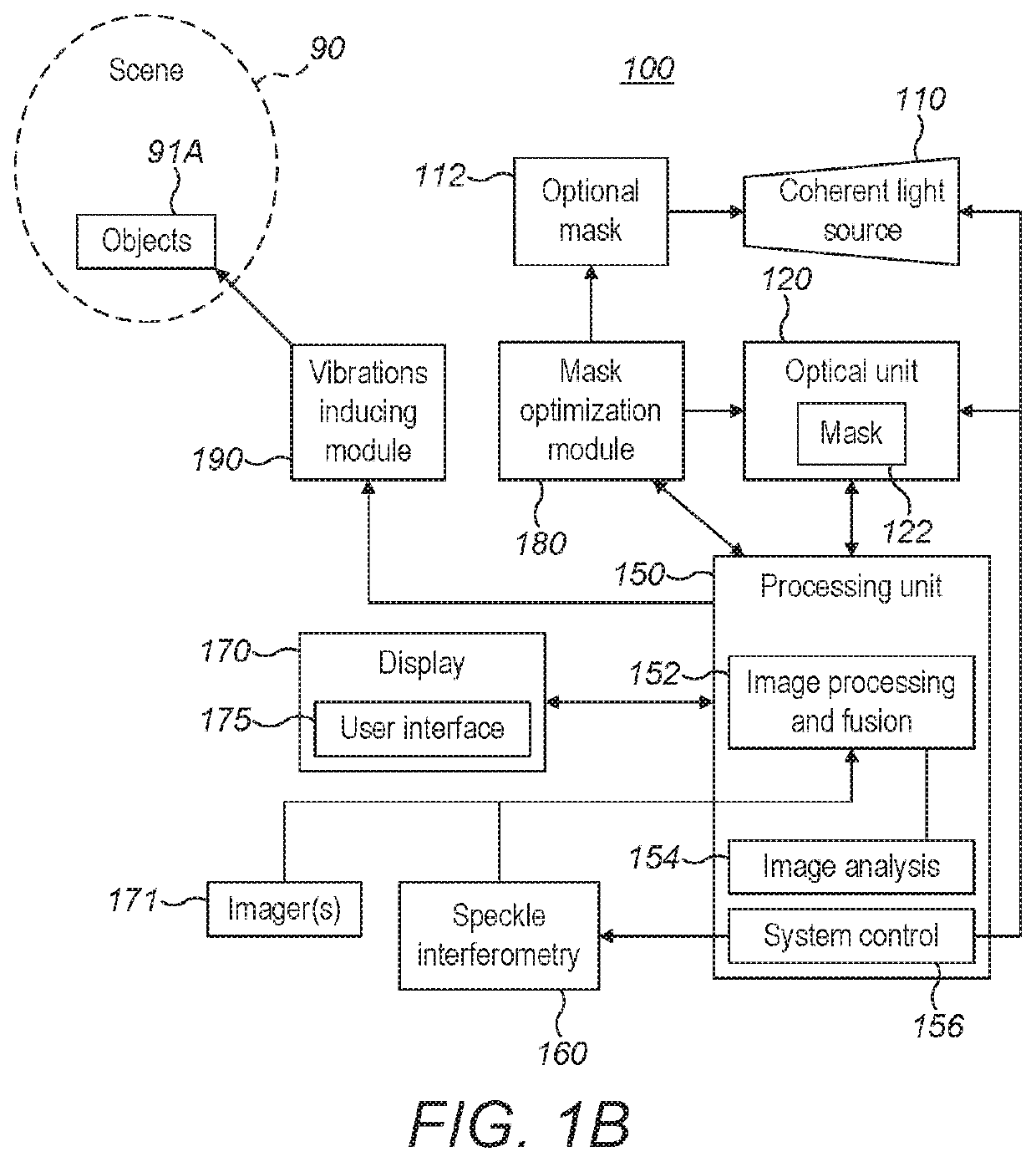
Systems and methods are provided for vibrations detection in a scene. Systems comprise at least one coherent light source configured to illuminate the scene, an optical unit configured to focus scattered light from the scene onto a pixelated detector, the detector configured to provide pixel intensity signals, and a processing unit configured to analyze the pixel intensity signals over the pixels of the detector to derive a vibration spectrum of elements in the scene that correspond to the pixels. The signal modulation at each pixel may be used to indicate the vibrations of the scene element(s) that corresponds to the pixel(s). Vibration information concerning the scene may be used to direct other methods of vibration measurements, such as speckle interferometry, according to derived vibration images of the scene.

Description

CROSS-REFERENCE TO RELATED APPLICATIONS[0001]This application is a National Phase Application of PCT International Application No. PCT / IL2017 / 050957, International Filing Date Aug. 28, 2017, entitled “OPTICAL DETECTION OF VIBRATIONS”, published on Mar. 8, 2018, under publication No. WO 2018 / 042424, which claims priority of Israel Patent Application Nos. 249474 and 247541, both filed on Aug. 29, 2016, all of which are hereby incorporated by reference in their entireties.BACKGROUND OF THE INVENTION1. Technical Field[0002]The present invention relates to the field of vibration sensing, and more particularly, to imaging of vibrations.2. Discussion of Related Art[0003]Remote sensing of small vibrational motion using speckle interferometry is a well-known and demonstrated method (see e.g., Zalevsky et al. 2009, Simultaneous remote extraction of multiple speech sources and heart beats from secondary speckles pattern, Optics express 17(24): 21566-21580). In this method a camera is used to c...

Claims


Application Information

Patent Timeline
Patent Type & Authority Patents(United States)
IPC IPC(8): G01B11/16G01H9/00G01B9/02
CPCG01H9/002G01B9/02084G01B9/02094G01B11/161G01B11/162G01B11/164
Inventor LEIZERSON, ILYANUSSINSON, DAN
Owner ELBIT SYST LAND & C4I
Learn More