Precise pressure measurement by vibrating an oval conduit along different cross-sectional axes

a technology of cross-sectional axes and precise pressure measurement, which is applied in the direction of instruments, specific gravity measurement, machines/engines, etc., can solve the problems of difficult installation requirements, bernoulli devices may disadvantageously require tubing penetration,

Inactive Publication Date: 2006-08-03
CARPENTER BRENT L
View PDF20 Cites 31 Cited by
  • Summary
  • Abstract
  • Description
  • Claims
  • Application Information

AI Technical Summary

Problems solved by technology

Bernoulli devices may disadvantageously require penetration into tubing; piezoelectric devices may be affected by material properties such as density, temperature, and viscosity.
Complex installation requirements and the need to periodically recalibrate for particular operating are problematic in the art.
These devices are limited in absolute accuracy by the inherent non-linearity of converting pressure to a mechanical displacement followed by converting displacement to an electronic signal required for a user interface.
This distortion puts exerts undesirable forces on the diaphragm either changing its displacement or its responsiveness to applied pressure.
These effects make the relationship between pressure and displacement inherently non-linear which, in turn, restricts the useful measurement range.
Typical diaphragm pressure sensors are limited to measuring pressures that are no more than ⅓ to 3 times the calibration standard.
Both approaches add cost and complexity not valued by industry.
These diaphragms are not typically suited for direct contact with industrial fluids.
The resulting dependency on uncontrollable environments factors and the inability to measure pressure precisely over operating conditions commonly found in industry further limit the accuracy of these devices.
Other prior art systems attempt to minimize this effect by selecting low viscosity oils as disclosed in U.S. Pat. No. 4,329,775 (issued May 18, 1982; the “'775 patent”); however, the use of low viscosity oils adds cost and complexity without substantially improving performance.
For example, the use of low viscosity oils reduces the useful temperature range of the sensor to less than requisite because the oils have undesirable property changes corresponding to temperatures outside a narrow temperature range.
Mechanical strain to electrical signal conversion contributes to non-linearity and reduced accuracy due to the low voltage analog signals and poor signal to noise ratio (SNR).
While these patents recognized t...

Method used


Image

  • Precise pressure measurement by vibrating an oval conduit along different cross-sectional axes
  • Precise pressure measurement by vibrating an oval conduit along different cross-sectional axes
  • Precise pressure measurement by vibrating an oval conduit along different cross-sectional axes

Examples


Embodiment Construction

[0063] While the invention is amenable to various modifications and alternative forms, a specific embodiment thereof is shown by way of example in the drawings and will herein be described in detail. It should be understood that the teaching is by way of example, not of limitations to the particular form disclosed.

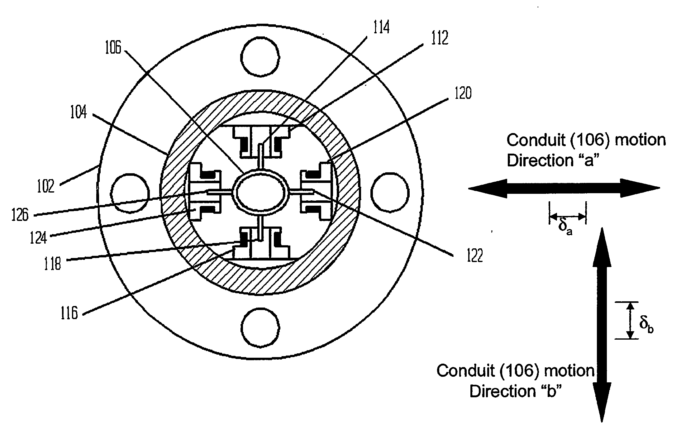
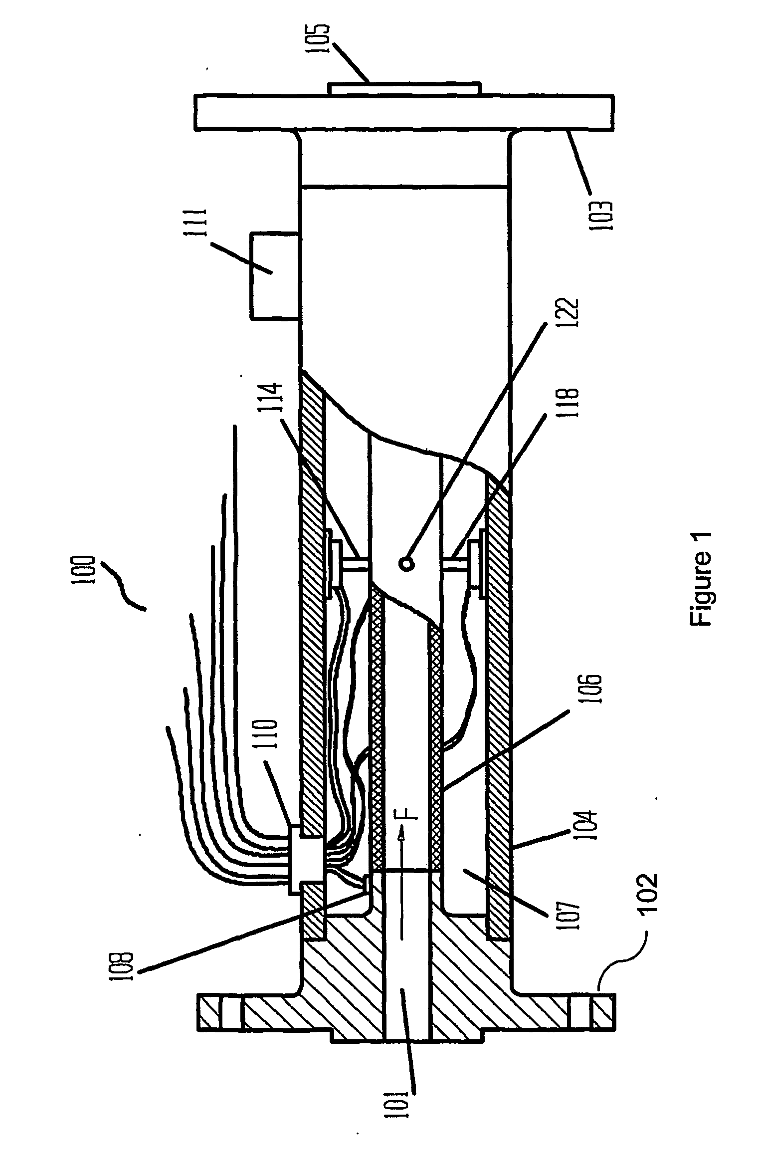
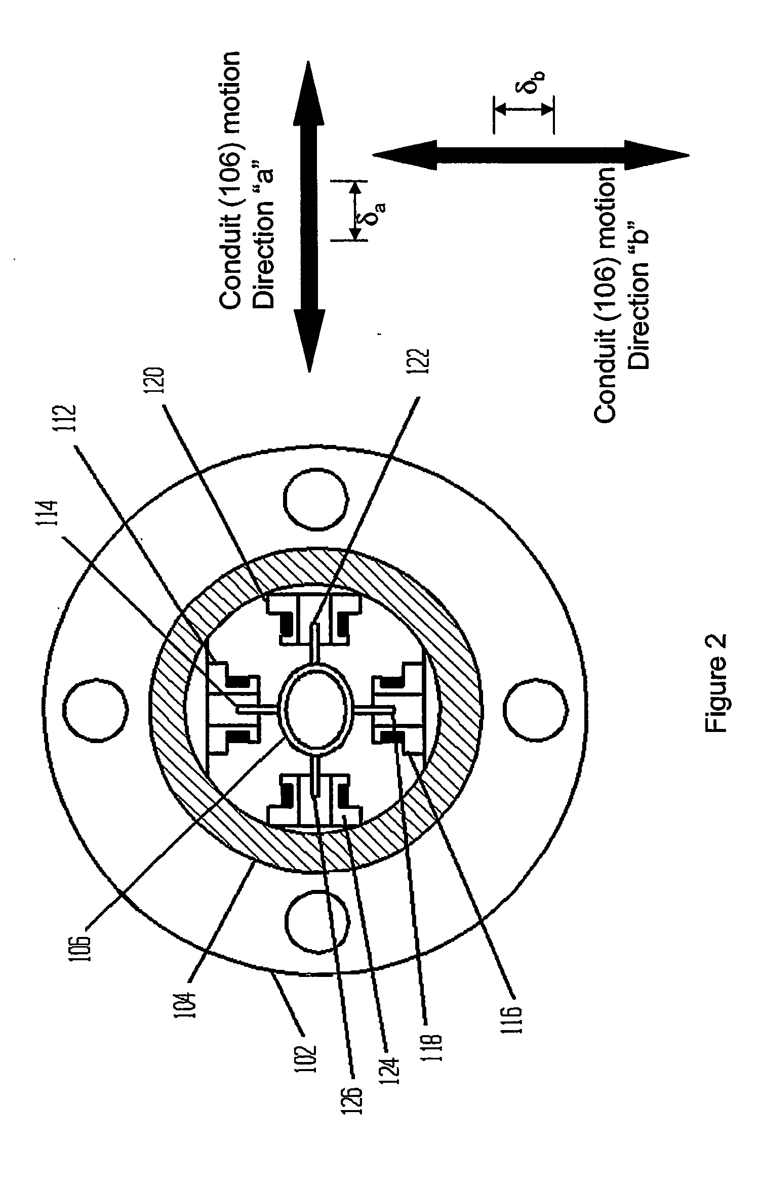
[0064] With reference now to the pressure figures and in particular with reference to FIG. 1, an embodiment hereof is shown in sensor 100, which may also be configured as a straight tube Coriolis flow meter, densometer, and viscosimeter. Sensor 100 is configured for determining a pressure of the fluid based on a squared ratio of detected frequencies resulting from vibration of conduit 106. In this embodiment, conduit 106 has an elliptical cross-section and is attached to ridged flanges 102 and 103. Typical wall thickness of conduit 106 would range between 0.006 inches to 0.25 inch, however, other wall thicknesses maybe used. Conduit 106 preferably comprises metal but coul...


PUM


Abstract

A conduit (106), with geometry designed to enhance pressure sensitivity, is vibrated at resonance in two modes along different cross-sectional axes (a, b). Measuring the change in the frequency ratio squared of the modes yields a substantially linear relationship to pressure that is substantially immune to other material properties and other environmental factors. Moments of inertia in different cross-sectional axes are related to pressure as a result of the elliptical or oral cross section of the conduit (106).

Description

CROSS REFERENCE TO RELATED APPLICATIONS [0001] This application is related to U.S. Provisional Patent Application No. 60 / 398,450 (filed Jul. 25, 2002; the “provisional”) and claims the benefit of the earlier filing date of the provisional.PROBLEM [0002] 1. Field of the Invention [0003] This invention relates to systems and methods for determining pressure and other properties of materials conveyed through a conduit. More specifically, the conduit is vibrated to yield a pressure value that is substantially immune to exogenous factors. [0004] 2. Discussion of the Related Art [0005] There are numerous systems reported in the prior art for determining a pressure measurement, such as Bernoulli devices and piezoelectric devices. Bernoulli devices may disadvantageously require penetration into tubing; piezoelectric devices may be affected by material properties such as density, temperature, and viscosity. Complex installation requirements and the need to periodically recalibrate for partic...

Claims


Application Information

Patent Timeline
IPC IPC(8): G01F23/00G01L11/04
CPCG01F1/8413G01F1/8422G01F1/8427G01F1/8431G01F1/8436G01F1/8463G01F1/849G01L9/0001G01L9/0008G01L11/04G01N9/002
Inventor CARPENTER, BRENT L.
Owner CARPENTER BRENT L
Why Eureka
Try Eureka