Integrated vibration measurement and analysis system

A technology of vibration signal and vibration energy level, which is used in vibration measurement in solids, analysis of materials, measurement devices, etc.

Active Publication Date: 2012-03-14
CSI TECH
View PDF19 Cites 30 Cited by
  • Summary
  • Abstract
  • Description
  • Claims
  • Application Information

AI Technical Summary

Problems solved by technology

[0043] In addition, there is a large divergence of undisclosed uses between the control device in the Inanaga et al. and Tomita patents and the mechanical vibration analyzer provided by the present invention

Method used


Image

  • Integrated vibration measurement and analysis system
  • Integrated vibration measurement and analysis system
  • Integrated vibration measurement and analysis system

Examples


Embodiment Construction

[0078] real-time digital integrator

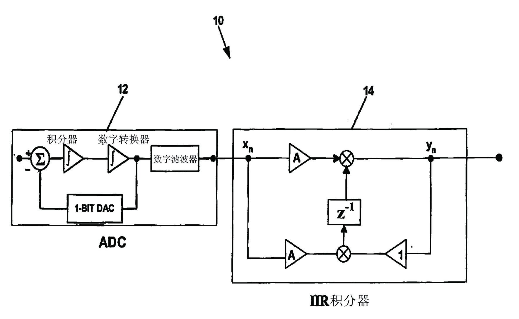
[0079] figure 1 The basic structure of an ideal real-time integrator system 10 is shown. This idealized system 10 includes an analog-to-digital converter (ADC) 12 and an ideal integrator 14 . The ideal integrator 14 can be realized by a difference equation containing only one multiplication operation, two addition operations and one memory location for each ADC clock cycle, expressed as follows:

[0080] (1)

[0081] where y n is the current output value, x n is the current input value, y n-1 x for the previous output value n-1 Enter the value for the previous. In equation (1), A is a constant taken from the conversion factor.

[0082] The difference equation (1) can be derived by putting the transfer function of an ideal integrator into the s-domain (complex frequency domain) according to the following equation:

[0083] (2)

[0084] in

[0085] (3)

[0086] Apply the bilinear transformation result to the follow...


PUM


Abstract

A vibration data collection system performs an integration or differentiation process on incoming digitized vibration data in real time. The system uses a digital Infinite Impulse Response (IIR) filter running at the input data rate to provide the integration or differentiation function. With this approach, the system reduces hardware complexity and data storage requirements. Also, the system provides the ability to directly integrate or differentiate stored time waveforms without resorting to FFT processing methods.

Description

technical field [0001] The invention relates to the field of detecting mechanical, electrical and electromagnetic fault states of machines by measuring machine vibrations in running machines, in particular to a system for real-time digital processing of time-domain signals reflecting machine vibrations. Background technique [0002] Problems with conventional analog integration in machine monitoring systems: [0003] Achieving conversion from one vibration-related signal, such as acceleration, to another, such as velocity or displacement, is a common requirement in vibration monitoring systems. A typical example could be the conversion from acceleration to velocity by integrating the acceleration signal. Similarly, the opposite conversion can be achieved by differentiating the velocity signal. In the past, these conversions have been accomplished using analog hardware filters. Such transformations can also be performed by software that performs a Fast Fourier Transform (F...

Claims


Application Information

Patent Timeline
Patent Type & Authority Applications(China)
IPC IPC(8): G01D21/00G01H1/00
CPCG01H1/003G01N29/11G01N29/14G01N29/449G01N2291/011G01N2291/0258G01H17/00G01M99/005
Inventor 约瑟夫·C·鲍德温
Owner CSI TECH
Why Eureka
Try Eureka