Method for detecting high speed rotating blade synchronous vibration parameters under speed change

A technology of synchronous vibration and parameter detection, applied in the direction of vibration measurement in solids, measuring vibration, measuring devices, etc., can solve the problems that the identification accuracy needs to be improved, the algorithm needs to be improved, etc., and achieve the effect of strong adaptability

Active Publication Date: 2010-01-13
ZHEJIANG ZHONGXIN POWER MEASUREMENT & CONTROL TECH
View PDF0 Cites 33 Cited by
  • Summary
  • Abstract
  • Description
  • Claims
  • Application Information

AI Technical Summary

Problems solved by technology

Various detection methods have their own advantages and disadvantages. Part of the vibration parameters can only be obta

Method used


Image

  • Method for detecting high speed rotating blade synchronous vibration parameters under speed change
  • Method for detecting high speed rotating blade synchronous vibration parameters under speed change
  • Method for detecting high speed rotating blade synchronous vibration parameters under speed change

Examples


Embodiment Construction

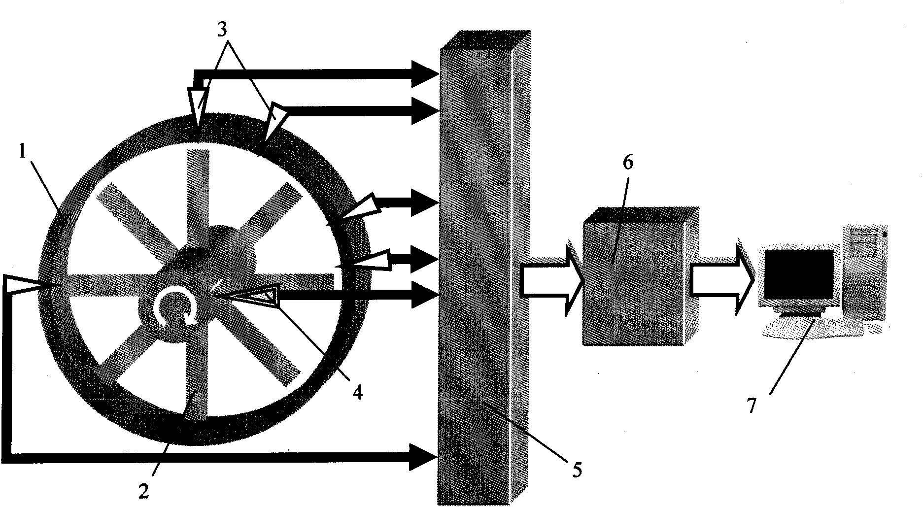
[0024] The technical scheme of the present invention is to select a suitable arbitrary distribution scheme through a sensor distribution optimization method according to the actual requirements of the rotating machine to be tested and the inherent characteristics of its blades, combined with certain prior knowledge. In the actual detection, the blade tip timing sensors are arranged according to this scheme, and the rotating machinery is controlled to run at roughly uniform speed. When the rotating speed passes through the blade synchronous resonance region, each blade tip timing sensor measures different phases and different displacements of the blade vibration. Combined with the different installation angles of each sensor, the synchronous resonance parameters of the blades can be accurately identified by using the frequency multiplication traversal algorithm.

[0025] The present invention will be further described in detail below in conjunction with the accompanying drawings...


PUM


Abstract

The invention relates to a method for detecting rotating mechanical blade vibration, in particular to a method for detecting high speed rotating blade synchronous vibration parameters under speed change, aiming at providing a method for detecting high speed rotating blade synchronous vibration parameters under speed change with high resolution preciseness and strong adaptability. The technical proposal of the invention comprises the following steps: step 1, determining a multi-sensor distribution scheme of blade tip timed vibration measurement: firstly pre-estimating the synchronous vibration frequency multiplication Ne possible to occur to the blade to be detected according to the actual detected rotating mechanical performance, and secondly determining the number and distribution condition of the mountable blade tip timed sensors and determining the mounting angles among the sensors according to the actual requirement of the rotating machinery; step 2, carrying out synchronous vibration measurement according to the above determined scheme; and step 3, adopting the traversal method to precisely obtain blade resonance frequency multiplication Ne, natural frequency fn and other parameters. The invention is mainly used for detecting rotating mechanical blade vibration.

Description

technical field [0001] The present invention relates to a method for detecting the vibration of rotating mechanical blades, more specifically, the present invention relates to a method for detecting synchronous vibration parameters of high-speed rotating blades with random distribution of multi-sensors under variable speed conditions based on the blade tip timing principle. Background technique [0002] Blade tip timing vibration measurement technology plays an important role in the field of real-time monitoring and fault diagnosis of rotating machinery. Higher requirements are put forward, which prompts it to develop in the direction of high-precision and comprehensive parameter detection. The blade tip timing vibration measurement technology is a non-contact detection method. Its basic principle is to install the blade tip timing sensor on the relatively stationary shell of the rotating machine, and use the sensor to measure the pulse signal generated when the blade passes...

Claims


Application Information

Patent Timeline
IPC IPC(8): G01H13/00G01H1/00
Inventor 段发阶欧阳涛李孟麟叶德超
Owner ZHEJIANG ZHONGXIN POWER MEASUREMENT & CONTROL TECH
Why Eureka
Try Eureka