Pressure washer

a washer and pressure washer technology, applied in the direction of cleaning processes and equipment, cleaning using liquids, chemistry apparatus and processes, etc., can solve the problems of potential safety hazards and easy increase of pressure in the battery cavity

Active Publication Date: 2022-07-05
TECHTRONIC CORDLESS GP
View PDF109 Cites 0 Cited by
  • Summary
  • Abstract
  • Description
  • Claims
  • Application Information

AI Technical Summary

Benefits of technology

[0006]The utility model aims to provide a pressure washer which is simple and ingenious in structural design, can effectively improve the sealing effect of a shell and prevent water from entering. In order to achieve the above object, the utility model provides a pressure washer, which comprises a water-sealed battery part and a main body part, wherein the water-sealed battery part comprises a shell formed by connecting a cover body and a cavity, and a battery pack is arranged in the shell.

Problems solved by technology

If the sealing effect is good, the pressure in the battery cavity is easily increased, and the high-pressure gas is not discharged, so that the potential safety hazard exists.

Method used


Image

  • Pressure washer
  • Pressure washer
  • Pressure washer

Examples


embodiment 1

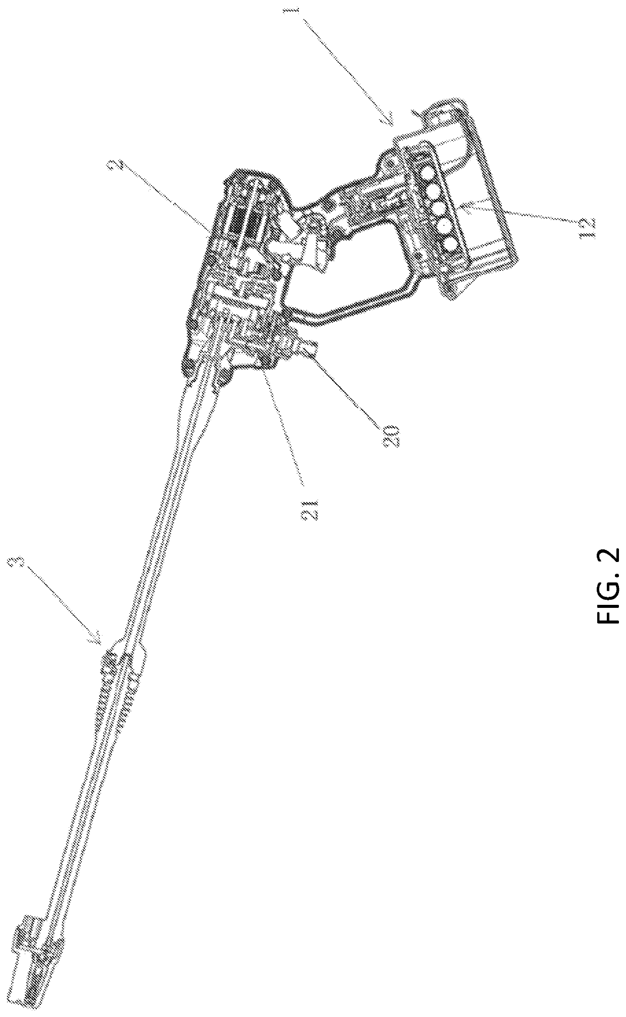
[0039]FIG. 2 is a schematic structural view of embodiment 1 of the pressure washer of the utility model, which from bottom to top sequentially comprises:

[0040]a water-sealed battery part 1: providing a main body part with power supply;

[0041]a main body part 2: forming a power mechanism into a water pump;

[0042]a nozzle part 3: for ejecting water pumped by the main body part 2 and being provided at one side of the main body part.

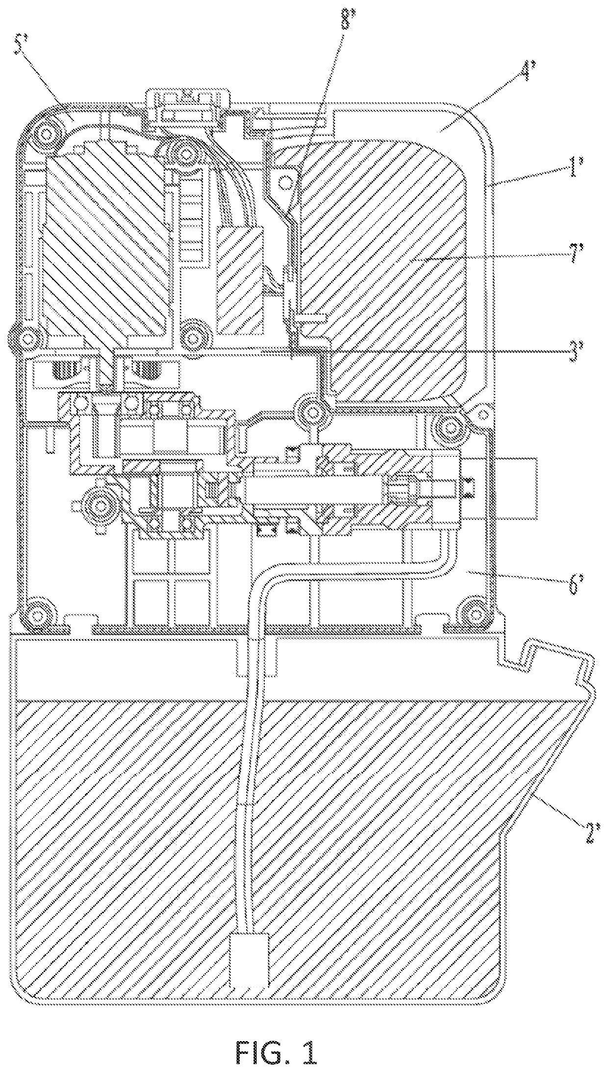
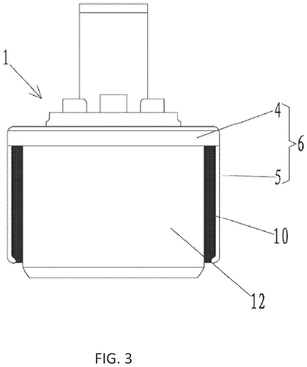
[0043]Referring to FIGS. 3 and 4, the water-sealed battery part 1 includes a shell 6 formed by connecting a cover body 4 and a cavity 5 open at upper end or open at side surface. In the present embodiment, the cavity 5 is opened at upper end, with the cover body 4 covering open end of the cavity 5.

[0044]A lower end of a rear surface of the cover body 4 is lower than a lower end of a front surface thereof, lower ends of a left side surface and a right side surface of the cover body 4 are symmetrically S-shaped, and a shape of upper open end of the cavity 5 is m...

embodiment 2

[0059]FIG. 10 is a schematic structural view of a water-sealed battery part of embodiment 2 of the pressure washer of the utility model. Most of the structure of the pressure washer in the embodiment is the same as that in the embodiment shown in FIG. 2, and the same points are not described in detail. The difference lies in that the water-sealed battery part of the embodiment comprises a cavity 5 open at an upper end, the cover body 4 covers on an open upper end surface of the cavity 5 through a hinge structure, and the hinge structure comprises a first hinge seat 48 arranged at an upper part of a side wall of the cavity 5, a second hinge seat 49 arranged at a lower part of a side wall of the cover body 4, and a pin shaft 50 arranged between the first hinge seat 48 and the second hinge seat 49. A seal is arranged between the cover body 4 and the cavity 5 and adopts a waterproof O-shaped sealing ring 51.

embodiment 3

[0060]FIG. 11 is a schematic structural view of a water-sealed battery part of embodiment 3 of the pressure washer of the utility model. Most of the structure of the pressure washer in the embodiment is the same as that in the embodiment shown in FIG. 10, and the same points are not described in detail. The difference lies in that the water-sealed battery part of the embodiment comprises a cavity 5 open at a side surface, and the cover body 4 covers on the open side surface of the cavity 5 through a hinge structure, a seal is arranged between the cover body 4 and the cavity 5, and the seal adopts a waterproof O-shaped sealing ring 51.


PUM


Abstract

The utility model discloses a pressure washer which comprises a water-sealed battery part and a main body part, wherein the water-sealed battery part comprises a shell formed by connecting a cover body and a lower cavity, and a battery pack is arranged in the shell. The pressure washer of the utility model is simple and ingenious in structural design, can effectively improve the sealing effect of the shell and prevent water from entering.

Description

[0001]This application claims the benefit of priority to Chinese Patent Application No. 201921954961.0, filed on Nov. 13, 2019, the disclosure of which is incorporated by reference herein in its entirety.TECHNICAL FIELD[0002]The invention relates to the technical field of high-pressure cleaning apparatus, in particular to a handheld pressure washer.BACKGROUND ART[0003]As shown in FIG. 1, the conventional high-pressure cleaning apparatus comprises an upper shell 1′ and a lower shell 2′, wherein the inner cavity of the upper shell 1′ is divided into a battery cavity 4′, a motor cavity 5′ and a pump cavity 6′ by a partition 3′, the lower shell 2′ is a water storage tank, and a battery pack 7′ is detachably accommodated in the battery cavity 5′; the partition 3′ is provided to prevent the cleaning liquid in the pump cavity 6′ from flowing into the battery cavity 4′ and the motor cavity 5′, and the sealing member 8′ is provided between the pump cavity 6′ and the battery cavity 4′ and bet...

Claims


Application Information

Patent Timeline
Patent Type & Authority Patents(United States)
IPC IPC(8): B05B15/14B05B9/01
CPCB05B15/14B05B9/01B05B9/0426B05B15/65B08B3/026Y02E60/10
Inventor HAZEL, JAREDZHI, LIANG YONGESCHRICH, SVENKANG, YANG SHAO
Owner TECHTRONIC CORDLESS GP
Why Eureka
Try Eureka