Retractable vortex generator system for an aircraft

a generator system and vortex generator technology, applied in power installations, air-flow influencers, transportation and packaging, etc., can solve the problems of reducing the efficiency of lifting surfaces, and achieving boundary layer separation

Active Publication Date: 2022-07-05
AIRBUS OPERATIONS SL
View PDF17 Cites 0 Cited by
  • Summary
  • Abstract
  • Description
  • Claims
  • Application Information

AI Technical Summary

Benefits of technology

[0015]In this entire document, it will be understood that the retractable vortex generator system is configured to be installed in an aerodynamic surface of an aircraft. When the system is installed on an aircraft, the skin of the system and the aerodynamic surface of the aircraft provide a clean aerodynamic surface. That is, the skin will be in line with the aerodynamic surface, providing aerodynamic continuity.
[0056]Using a magnetic interface for actuating the torsion springs with magnetic means such as electromagnets provides the system with improved robustness and intrinsic safety, as the reduction of components means lower risk of sources of failure. Further, magnetic coupling allows fine tuning and better stabilization of the torsion springs, which results in a more precise control of the rotation of the plate. Also, the reduction of mechanical connections and actuators suppress the drawbacks associated with its use, such as noise, wear and unwanted vibrations, everything allows while reducing the frequency and extent of maintenance operations.

Problems solved by technology

These effects can result in reduced efficiency of lifting surfaces, or even stalling at low flight speeds and high angles of attack.
In particular, the delay in the separation of the boundary layer, is achieved due to the fact that vortex generators transport fluid with high momentum present in the upper and outer parts of the boundary layer, as vortices, down to the lower momentum zone which is closer to the aerodynamic surface.
Therefore, the flow detachment occurs prior to the interaction with the ailerons, what renders them ineffective.
Regarding the mechanical implementation of vortex generators, they are normally mounted or glued directly on the aerodynamic surface of the aircraft, thus being present interfering with the airstream in all the stages of flight, even when they are not needed.

Method used


Image

  • Retractable vortex generator system for an aircraft
  • Retractable vortex generator system for an aircraft
  • Retractable vortex generator system for an aircraft

Examples


Embodiment Construction

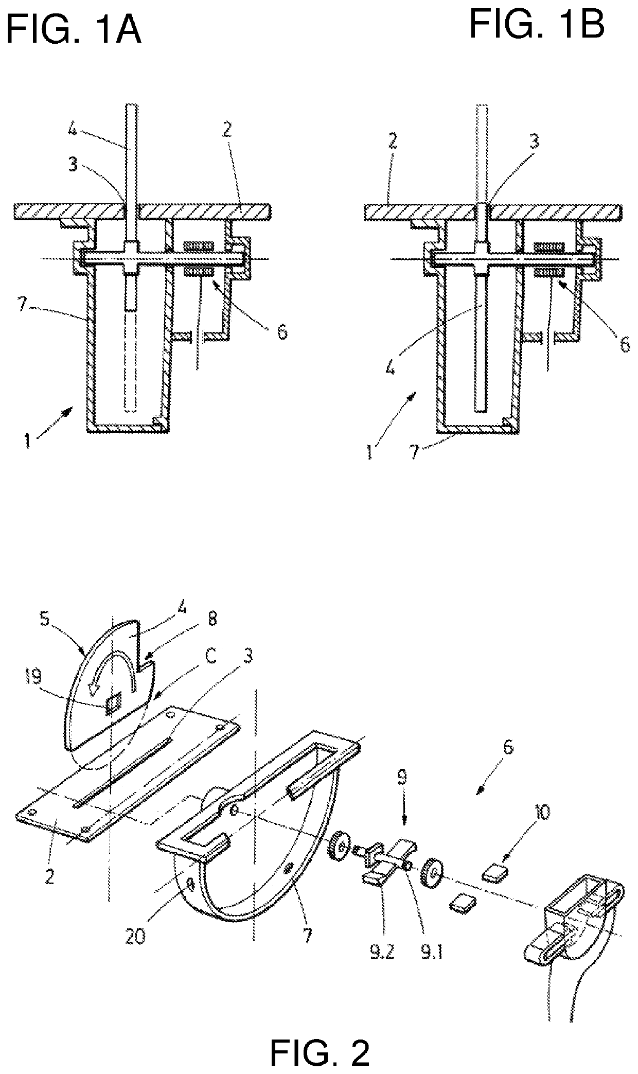
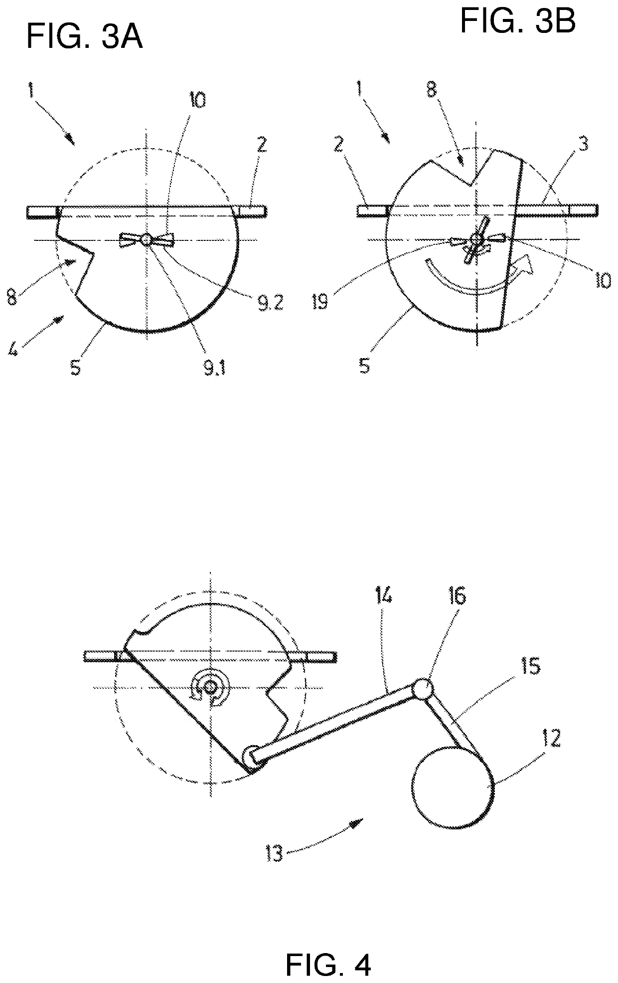
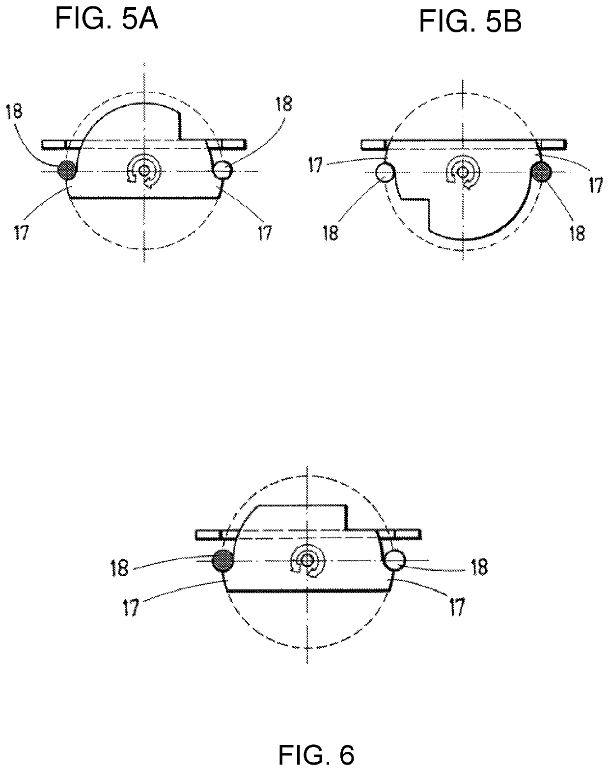
[0066]FIGS. 1A, 1B and 2 show schematic representations of an embodiment of the retractable vortex generation system (1) according to the present invention. In particular, FIGS. 1A and 1B show two schematic views of the system (1) corresponding to the first (1A) and the second (1B) position of the plate (4), respectively. FIG. 2 shows and exploded view of the elements of the system (1).

[0067]These figures show a skin (2), which is adapted to be connected to the external surface of an aircraft (100), being in line with the surface, once the system (1) has been implemented therein, thus providing aerodynamic continuity.

[0068]Further, the skin (2) comprises a slot (3). The slot (3) allows the plate (4) to protrude therethrough, rotated by the driving means (6), so as to stand in the way of the surrounding air flow and energize the local boundary layer, in the event that vortex generation is needed to prevent the air flow from detaching from the surface of the aircraft (100).

[0069]In FI...


PUM

PropertyMeasurementUnit
circular shapeaaaaaaaaaa
polarityaaaaaaaaaa
store potential energyaaaaaaaaaa

Abstract

A retractable vortex generator system for an aircraft. The system comprises a skin, a slot arranged on the skin, a plate comprising a contour configured for energizing the boundary layer of an air current, and driving means configured for rotating the plate between a first and a second position. In the first position at least part of the contour of the plate protrudes through the slot, and in the second position the plate is retracted within the slot.

Description

CROSS-REFERENCES TO RELATED APPLICATIONS[0001]This application claims the benefit of the European patent application No. 19382487.7 filed on Jun. 12, 2019, the entire disclosures of which are incorporated herein by way of reference.FIELD OF THE INVENTION[0002]The present invention belongs to the field of air flow control, in particular to the field of boundary layer manipulation technology for aerodynamic surfaces by means of vortex generation. More specifically, the invention is of special relevance in the aeronautic industry for delaying separation of the boundary layer while minimizing the drag generated. Particularly, the present invention provides a retractable vortex generator system for an aircraft.BACKGROUND OF THE INVENTION[0003]In the aeronautic industry, vortex generators have been used for many years as passive flow control devices which are installed on an outer surface of an aerodynamic body such as an aircraft wing to delay separation of the boundary layer, thus contr...

Claims


Application Information

Patent Timeline
Patent Type & Authority Patents(United States)
IPC IPC(8): B64C23/06B64D41/00H01F7/06H01F7/20
CPCB64C23/06B64D41/00H01F7/064H01F7/20B64C21/00B64C1/12B64C23/072B64C23/076Y02T50/10
Inventor ARANA HIDALGO, ALBERTO
Owner AIRBUS OPERATIONS SL
Why Eureka
Try Eureka