

Method for operating a batch furnace comprising the preheating of a fluid upstream of the furnace
a batch furnace and preheating technology, applied in the direction of furnaces, lighting and heating apparatus, combustion types, etc., can solve problems such as heat shock
- Summary
- Abstract
- Description
- Claims
- Application Information
AI Technical Summary
Benefits of technology
Problems solved by technology
Method used
Image

Examples
Embodiment Construction
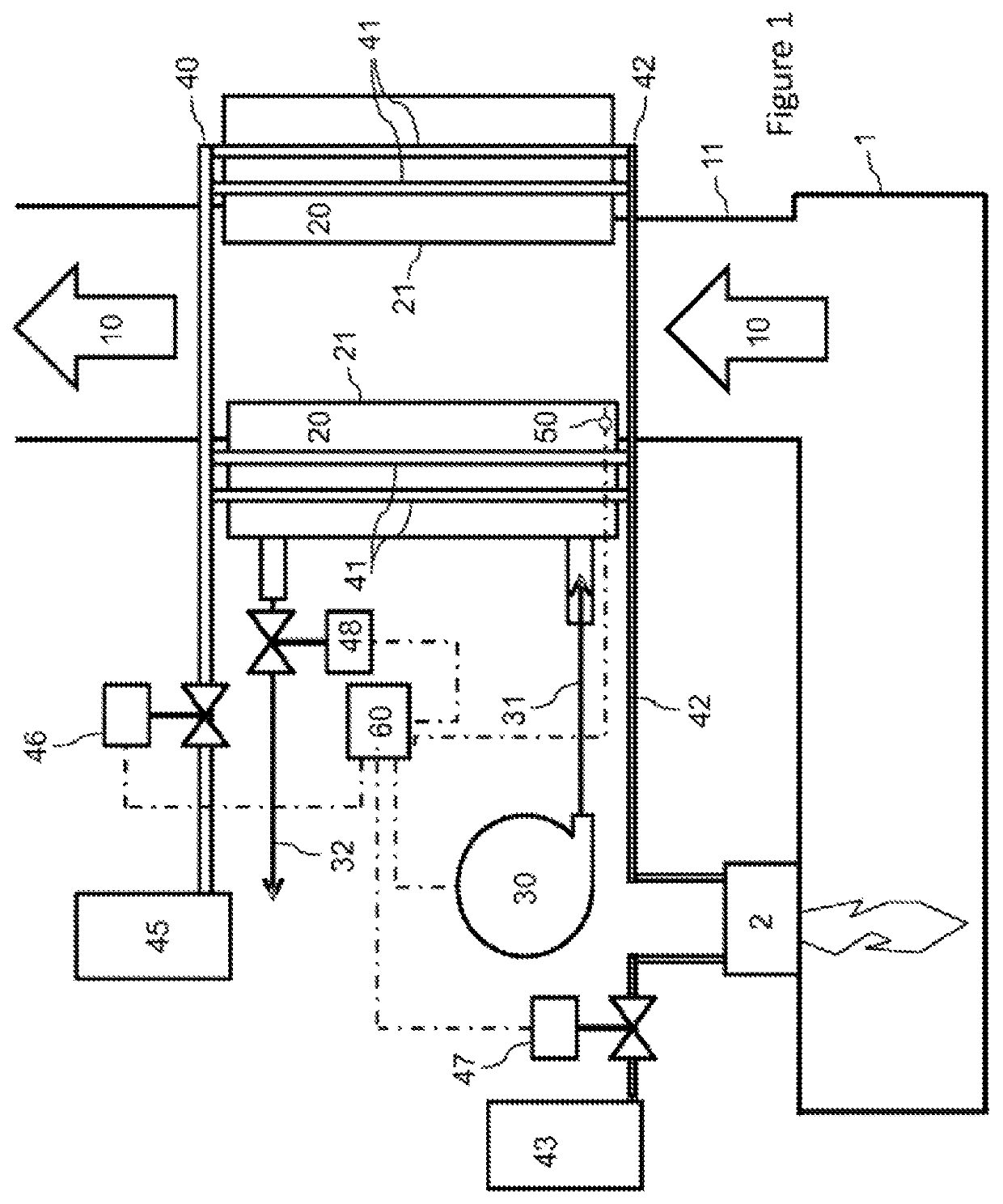
[0061]The batch furnace 1 is provided with at least one burner 2 for the combustion of a fuel with an oxygen-rich oxidant, for example an oxidant having an oxygen content of at least 97 vol %.
[0062]Although a single burner is shown in FIG. 1, the furnace may comprise several such burners 2. The position of the burner(s) 2 in the furnace depends on the type of furnace and on the process for which the furnace is intended. For example, in a rotary furnace, it is common to have a burner positioned in the longitudinal end(s) of the cylinder forming the rotary furnace. In a (non-rotary) reverberatory furnace, the burner or burners may, for example, be mounted in the roof, in the lateral walls and / or in the transverse walls.
[0063]The fuel, for example natural gas, is supplied by a fuel source 43 and the oxidant by an oxidant source 45 such as a liquefied oxygen tank or an air separation unit.
[0064]When a combustion of the fuel with the oxidant takes place in the furnace 1, which is the cas...
PUM
 Abstract
Description
Claims
Application Information