Measurement of material properties under local tensile stress through contact mechanics

a contact mechanics and material technology, applied in the field of contact mechanics, can solve the problems of material with a large crack, and material with a large crack, and material size is too large to be feasibl

Active Publication Date: 2022-07-05
MASSACHUSETTS MATERIALS TECH
View PDF13 Cites 1 Cited by
  • Summary
  • Abstract
  • Description
  • Claims
  • Application Information

AI Technical Summary

Benefits of technology

[0014]In one embodiment of the invention, an apparatus for performing a contact mechanics test on a substrate that comprises a stylus having a contact profile configured to deform the substrate by generating microstructure changes, microvoid formation, cracking or other changes in the substrate. Some of these micromodifications remain in the residual substrate surface after the stylus is removed. The stylus generates a stretch zone shaped to engage against the substrate and promote tensile stresses in at least one direction. In another embodiment, the stylus further comprises a stress passage that further facilitates the generation of a zone of tension and / or helps to preserve the micromodifications after their formation. In other embodiments, the stylus is coupled to an engagement mechanism that is configured to maintain the penetration of the stylus within the substrate, an engagement mechanism configured to move the stylus relative to the substrate surface, an alignment mechanism configured to maintain a desired orientation of the stylus with respect to the substrate, and / or a substrate surface measurement device containing one or more instruments to measure characteristics of the residual substrate surface.

Problems solved by technology

However, strength based design omits key features that control how materials fail.
Thus, a material with a large crack will exhibit a reduced strength compared to a material with a smaller crack.
However, for materials with high fracture toughness such as aluminum or steel, the fracture process zone is large and meeting small-scale yielding conditions would require specimen sizes that are too large to be feasible in practice, requiring the use of elastic-plastic fracture mechanics (EPFM).
The fracture toughness experiments described above are destructive tests which can only be performed in a laboratory, are expensive, and require specialized equipment to monitor the dimensions of a growing crack under loading.
Empirical relationships with fracture toughness used in LEFM or EPFM can be established, but their accuracy and transferability is limited.
This value is critical for engineering applications where lower service temperatures could lead to a greater risk of crack propagation.
These assumptions are not well supported for ductile metals where significant plastic deformation occurs near contact.
These machining concepts are not widely used in practice because the stress-strain field induced in the material consist of large hydrostatic compression and shear, which differs from the traditional tensile crack-opening mode that leads to many material failures.

Method used


Image

  • Measurement of material properties under local tensile stress through contact mechanics
  • Measurement of material properties under local tensile stress through contact mechanics
  • Measurement of material properties under local tensile stress through contact mechanics

Examples


Embodiment Construction

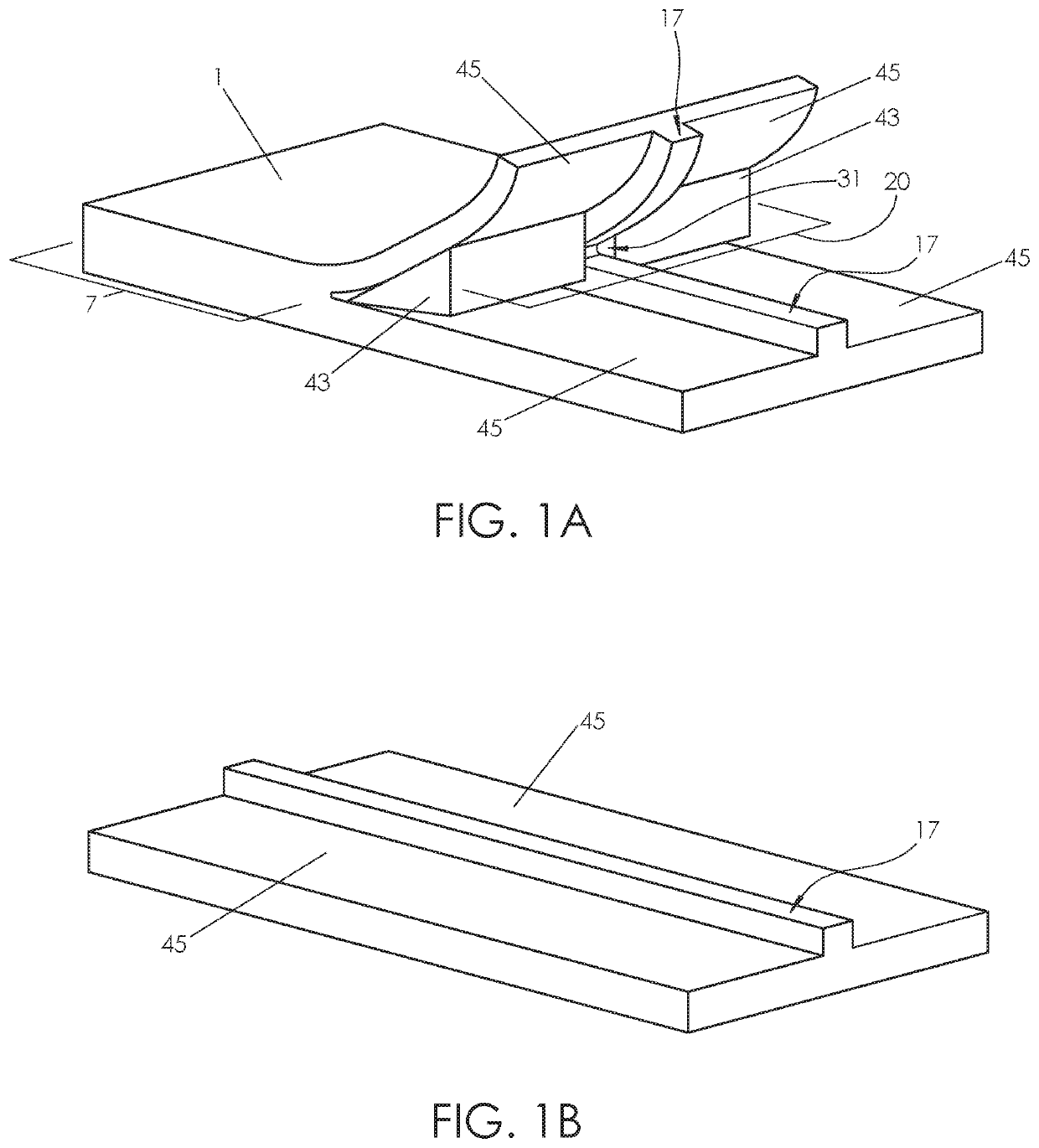
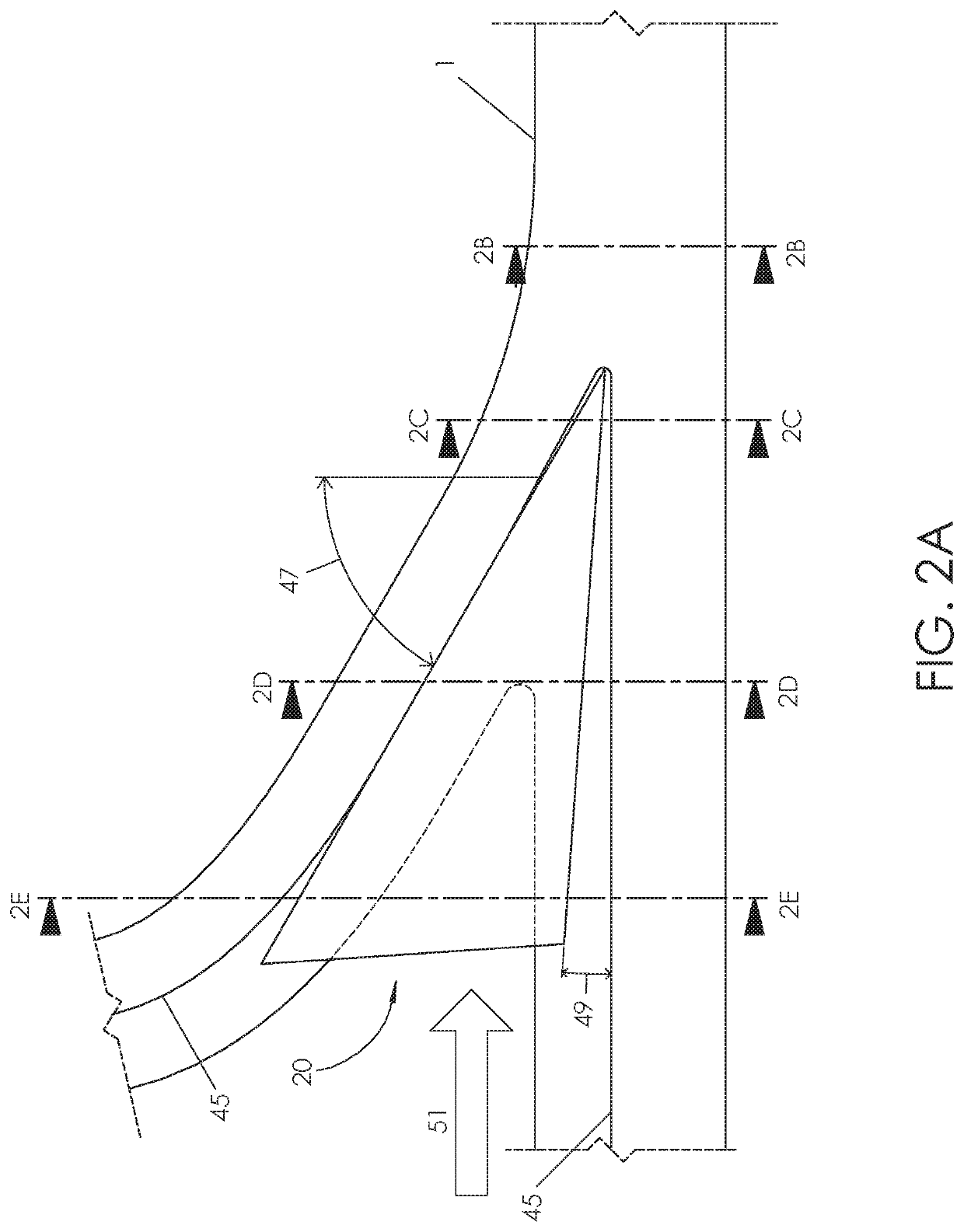
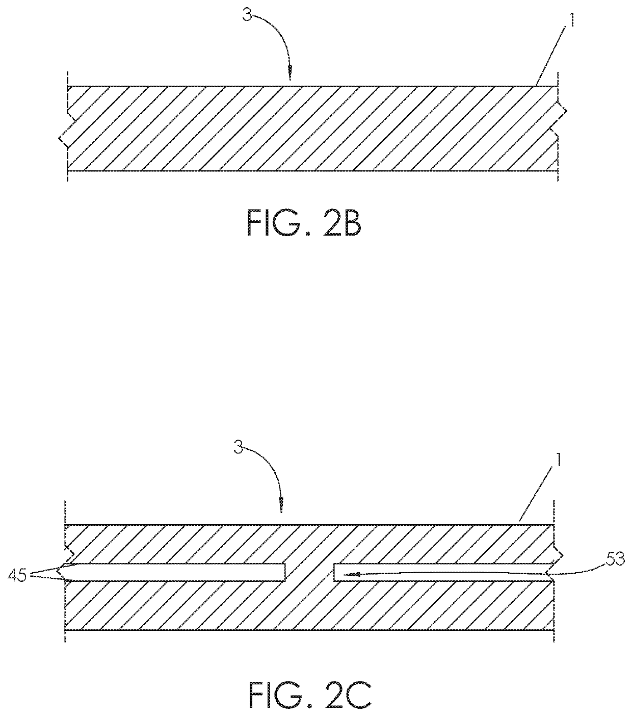
[0010]In one embodiment of the invention, an apparatus for performing a contact mechanics test in a substrate includes a stylus having at least two contact elements. Each contact element has a contact profile, and the contact elements are disposed in the stylus to define a stretch passage therebetween. The stylus is configured to deform the substrate so as to cause the substrate to flow between the contact elements and induce tension in the substrate within the stretch passage to generate and preserve micromodifications in the substrate.

[0011]In related embodiments, the stylus may be further configured to generate and preserve the micromodifications in multiple orientations, which may include (a) an opening that is either normal or transverse to an undeformed surface of the substrate as the stylus travels parallel to the undeformed surface, and / or (b) an opening that is normal or transverse to the direction of travel during an indentation mode. The apparatus may further include an e...


PUM

PropertyMeasurementUnit
attack angleaaaaaaaaaa
tensionaaaaaaaaaa
movementaaaaaaaaaa

Abstract

An apparatus for performing a contact mechanics test in a substrate includes a stylus having at least two contact elements. Each contact element has a contact profile, and the contact elements are disposed in the stylus to define a stretch passage therebetween. The stylus is configured to deform the substrate so as to cause the substrate to flow between the contact elements and induce tension in the substrate in order to generate and preserve micromodifications in the substrate. Methods of performing a contact mechanics test using the apparatus are also provided.

Description

CROSS REFERENCE TO RELATED APPLICATIONS[0001]The present application is a continuation application of International Application No. PCT / US2016 / 065960 filed Dec. 9, 2016, which claims the benefit of U.S. Provisional Patent Application No. 62 / 265,234 filed Dec. 9, 2015, the disclosures of which are incorporated by reference herein in their entirety.TECHNICAL FIELD[0002]The present invention relates to the use of contact mechanics to gain data and information related to how a material resists micromodifications when subjected to a stress field that includes tensile stresses in at least one direction.BACKGROUND ART[0003]U.S. Patent Application Publication No. 2016 / 0258852 entitled “Contact Mechanic Tests Using Stylus Alignment to Probe Material Properties” describes the background art and is incorporated by reference herein in its entirety. Specifically, the publication describes the use of an alignment mechanism and engagement mechanism to perform a frictional sliding test.[0004]For sa...

Claims


Application Information

Patent Timeline
Patent Type & Authority Patents(United States)
IPC IPC(8): G01N3/44G01N3/46G01N3/60G01N19/06G06N5/04
CPCG01N3/44G01N3/46G01N3/60G01N19/06G01N2203/0053G01N2203/0066G01N2203/0078G06N5/04G01N3/42G01N2203/0062
Inventor BELLEMARE, SIMON C.PALKOVIC, STEVEN D.WILLEY, BRENDON M.SOUCY, PHILLIP A.
Owner MASSACHUSETTS MATERIALS TECH
Why Eureka
Try Eureka