Homogenizer, illuminating optical system, and illuminator

a technology of illuminating optical system and homogenizer, which is applied in the direction of instruments, lighting and heating apparatus, lenses, etc., can solve the problems of poor mass productivity, poor distribution of illumination-plane intensity, and difficulty in die forming to produce lens arrays therefrom

Active Publication Date: 2022-07-05
AGC INC
View PDF23 Cites 0 Cited by
  • Summary
  • Abstract
  • Description
  • Claims
  • Application Information

AI Technical Summary

Benefits of technology

[0059]The present invention can provide a homogenizer which is small and has a satisfactory utilization efficiency and which can emit light showing high evenness on irradiation planes, and an illuminating optical system and an illuminator.
[0060]Furthermore, the present invention can provide a homogenizer by which divergent light having an uneven light-intensity distribution emitted by a laser light source can be projected at a maximum diffusion angle of 120 or larger on an irradiation plane so as to result in a light-intensity distribution as even as 85% or more while a high condensing efficiency is maintained, and an illuminating optical system and an illuminator employing the homogenizer. In particular, the present invention can provide a homogenizer showing such properties for divergent light having a Gaussian intensity distribution emitted by a semiconductor laser light source, and an illuminating optical system and an illuminator employing the homogenizer.

Problems solved by technology

Synthetic quartz has a softening temperature as high as 1,000° C. or higher and it is difficult to produce a lens array therefrom by die forming.
This configuration is poor in mass productivity.
If some of the divergent light which has entered the aperture of the convex lens 621a reaches the outside of the convex lens 621b, which is paired with the convex lens 621a, the some of the divergent light become stray light, which is not condensed so as to strike on the desired irradiation plane, resulting in a poor illumination-plane intensity distribution and a decrease in light utilization efficiency.
In addition, since spherical convex lenses having a large numerical aperture have off-axial aberration and poor condensing properties, it is preferred to employ an aspherical shape.
Thus, the illuminating optical system 210 is difficult to be reduced in size.

Method used


Image

  • Homogenizer, illuminating optical system, and illuminator
  • Homogenizer, illuminating optical system, and illuminator
  • Homogenizer, illuminating optical system, and illuminator

Examples


embodiment 1

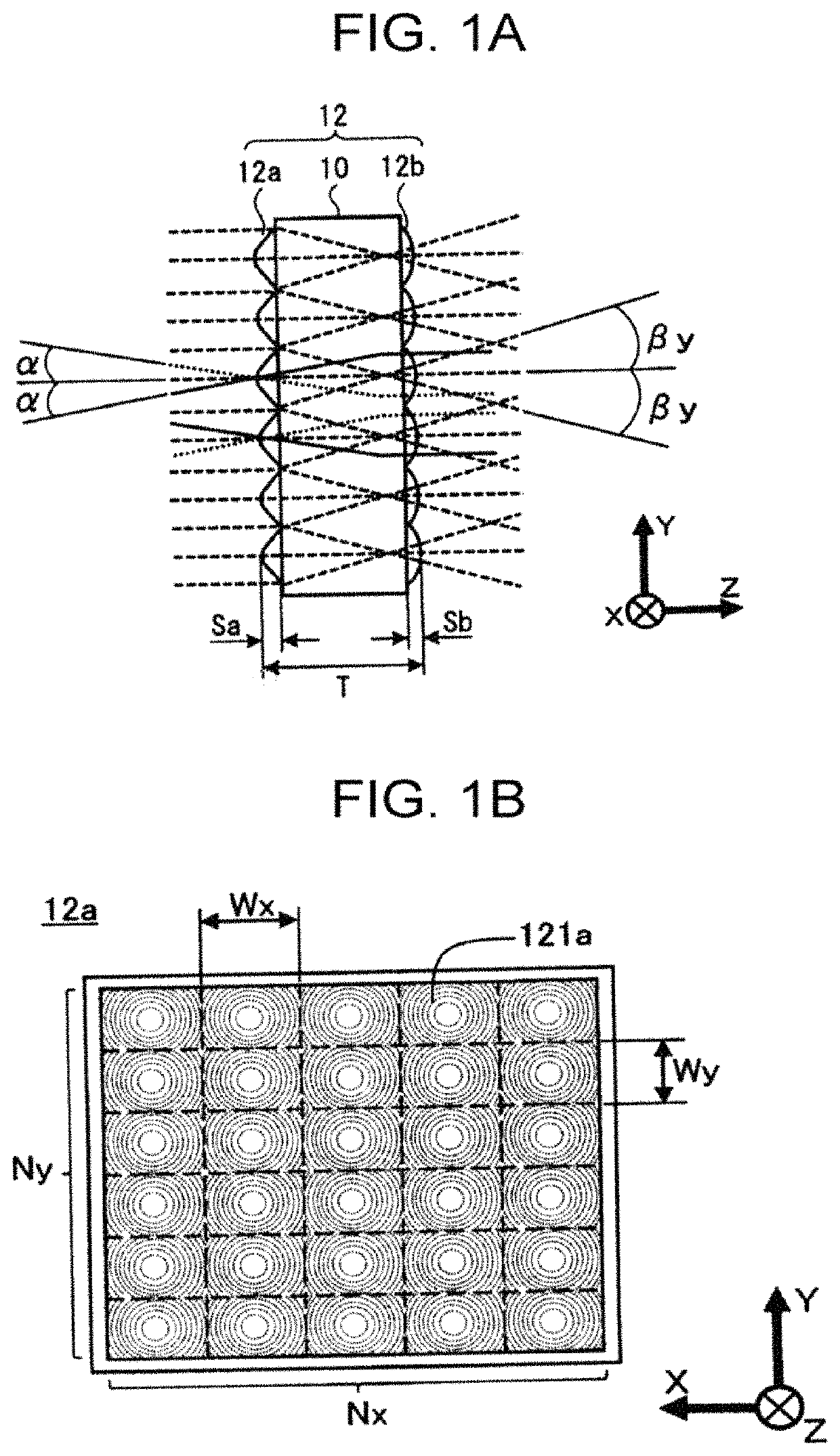
[0090]Examples of embodiments of the present invention are explained below by reference to drawings. FIG. 1A and FIG. 1B are respectively a cross-sectional view and a plan view which show an example of a homogenizer according to a first embodiment. As FIG. 1A shows, the homogenizer 12 according to this embodiment includes a light-transmitting substrate 10 having a flat-plate shape and a first convex-lens array 12a and a second convex-lens array 12b, which are disposed respectively on two surfaces (first surface and second surface) of the light-transmitting substrate 10.

[0091]In the first convex-lens array 12a and the second convex-lens array 12b, convex lenses 121a constituting the first convex-lens array are respectively paired with convex lenses 121b constituting the second convex-lens array. More specifically, the first convex-lens array 12a and the second convex-lens array 12b are each a gap-less lens array in which flat portions between adjoining convex lenses are small, and ea...

embodiment 2

[0125]Next, a second embodiment of the present invention is explained. FIG. 5A and FIG. 5B are respectively a schematic cross-sectional view and a schematic plan view which show an example of convex lenses 221a constituting a first convex-lens array 22a of a homogenizer 22 according to the second embodiment. As FIG. 5A and FIG. 5B show, the homogenizer 22 according to this embodiment differs from the homogenizer 12 according to the first embodiment in the configuration and function of the convex lenses 221a constituting the light-entrance-side first convex-lens array 22a. The configurations and functions of a light-transmitting substrate 20 and convex lenses 221b constituting a light-emission-side second convex-lens array 22b are the same as those of the light-transmitting substrate 10 and the convex lenses 121b constituting the light-emission-side second convex-lens array 12b in the first embodiment.

[0126]The convex lens 221a according to this embodiment has a phase diffraction gra...

third embodiment

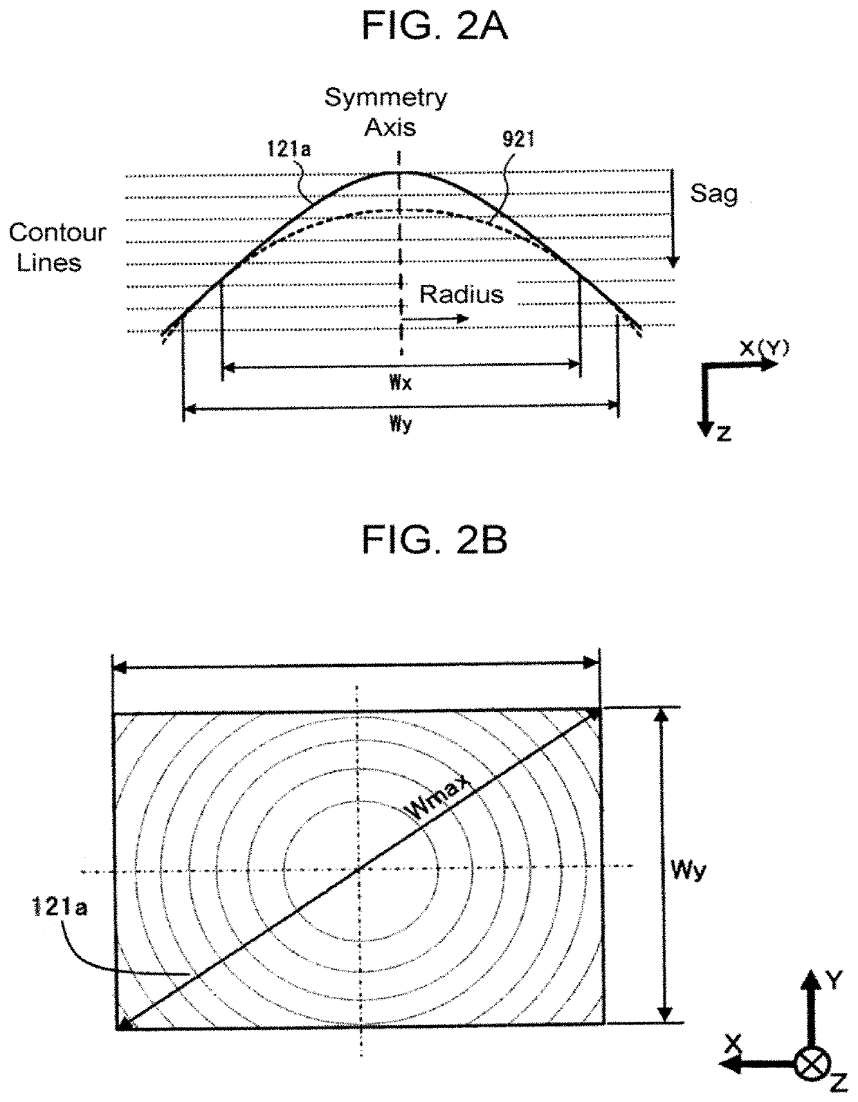
[0137]The homogenizers (12 and 22) according to the first and second embodiments are each configured of a first convex-lens array (12a or 22a) and a second convex-lens array (12b or 22b) each obtained by arraying convex lenses which each have a lens surface symmetric with respect to the axis and have an XY-plane outer shape that is quadrilateral (Wx×Wy). Because of this, the convex-lens surface has a maximum diameter and a maximum depth (maximum sag value) along diagonal directions of the quadrilateral shape. In the case where the outer shape is square (W=Wx=Wy), the maximum width (Wmax) of each convex lens is expressed by the formula (7). Spherical lenses have a lens depth being twice as compared with the directions of the sides (X axis and Y axis) of the square.

[Math. 2]

Wmax=√{square root over ((Wx2+Wy2))}=2·W  (7)

[0138]Furthermore, in each convex-lens array, quadrilateral convex lenses each having a maximum inclination angle at the corners are arranged such that four convex-lens ...


PUM


Abstract

A homogenizer includes a convex-lens array pair including a first convex-lens array disposed on a light entrance side and a second convex-lens array disposed on a light emission side. The first convex-lens array and the second convex-lens array are disposed so as to face each other such that each of the convex-lens arrays has a lens surface opposed to each other outward or inward. The first convex-lens array includes a plurality of first convex lenses in an array arrangement. The second convex-lens array includes a plurality of second convex lenses in an array arrangement. The first convex lens has an average internal transmission angle for incident light entering a lens-surface center region in the lens cross-section and being in parallel with the symmetry axis being equal to or more than 1.3 times an average internal transmission angle of a spherical convex lens.

Description

TECHNICAL FIELD[0001]The present invention relates to a homogenizer which converts an incident light having an uneven light-intensity spatial distribution into a light having an even light-intensity distribution on an irradiation plane, and to an illuminating optical system and an illuminator each including the homogenizer.BACKGROUND ART[0002]A homogenizer including a pair of lens arrays called integrator lenses or fly-eye lenses is a common technique for enabling illuminating optical systems, such as liquid-crystal projectors, which are for enlarging and projecting images produced by liquid-crystal display elements, and exposure devices, to attain an even light-intensity distribution on irradiation planes.[0003]FIG. 23A and FIG. 23B are cross-sectional views showing one example of illuminating optical systems used in liquid-crystal projectors. The illuminating optical system 200 shown in FIG. 23A and FIG. 23B includes a discharge lamp 50, a parabolic mirror 51, a homogenizer 52 inc...

Claims


Application Information

Patent Timeline
Patent Type & Authority Patents(United States)
IPC IPC(8): G03B21/00G03B21/20G02B3/00G02B5/18G02B27/30
CPCG03B21/208G02B3/0062G02B5/1814G02B27/30G03B21/2033G02B2003/0093F21V5/04G02B19/00F21S2/00G02B3/005G02B3/0056G02B27/0961
Inventor OOI, YOSHIHARUTASHIMA, KOICHIONO, KENSUKEKOYANAGI, ATSUSHI
Owner AGC INC
Why Eureka
Try Eureka