
Microneedle template and microneedle prepared using the same

a microneedle and template technology, applied in the field of microneedle templates, can solve the problems of needle phobia, temporary drug injection, uneven surface, weak hardness and strength, etc., and achieve the effects of high uniformity, excellent stability, and high evenness

Active Publication Date: 2021-01-26
S SKIN CO LTD
View PDF11 Cites 0 Cited by
  • Summary
  • Abstract
  • Description
  • Claims
  • Application Information

AI Technical Summary

Benefits of technology

The present invention relates to a microneedle template and a method for preparing microneedles using the template. The microneedle template has high stability, evenness, and is suitable for mass production of microneedles. The method reduces manufacturing costs compared to conventional methods and the resulting microneedle has high uniformity and high skin penetration. Additionally, the microneedle template can be used semipermanently for preparing multiple negative molds.

Problems solved by technology

As such, a metallic syringe has been used for at least 150 years to inject a liquid-phase drug by penetrating the epidermis, but there have been disadvantages such as causing pain, temporary drug injection, and needle phobia.
The microneedle array mold is typically formed of silicon and thus is weak in hardness and strength and has an uneven surface.

Method used


Image

  • Microneedle template and microneedle prepared using the same
  • Microneedle template and microneedle prepared using the same
  • Microneedle template and microneedle prepared using the same

Examples


example 1

on of Microneedle Template

[0115]A tungsten carbide substrate was ground with a diamond-coated wheel to form a microneedle shape on the substrate (First grinding). After the first grinding, the cross section of the microneedle shape had a tetragonal shape only, as shown in FIGS. 5A to 5C.

[0116]Then, the microneedle shape was further ground with a diamond wheel, and thus the microneedle shape had a portion having a tetragonal cross section and a portion having a hexagonal cross section, as shown in FIGS. 6A to 6C and FIGS. 7A and 7B (Second grinding).

[0117]After the first grinding and the second grinding, a microneedle template was pre-treated to remove foreign materials from the surface and then washed to well form a diamond layer on the surface of the microneedle shape.

[0118]Then, after the first grinding and the second grinding, each microneedle template was located in a CVD coating chamber having an internal temperature of about 2,000° C., diamond was deposited to a thickness of 1...

example 2

on of Microneedle

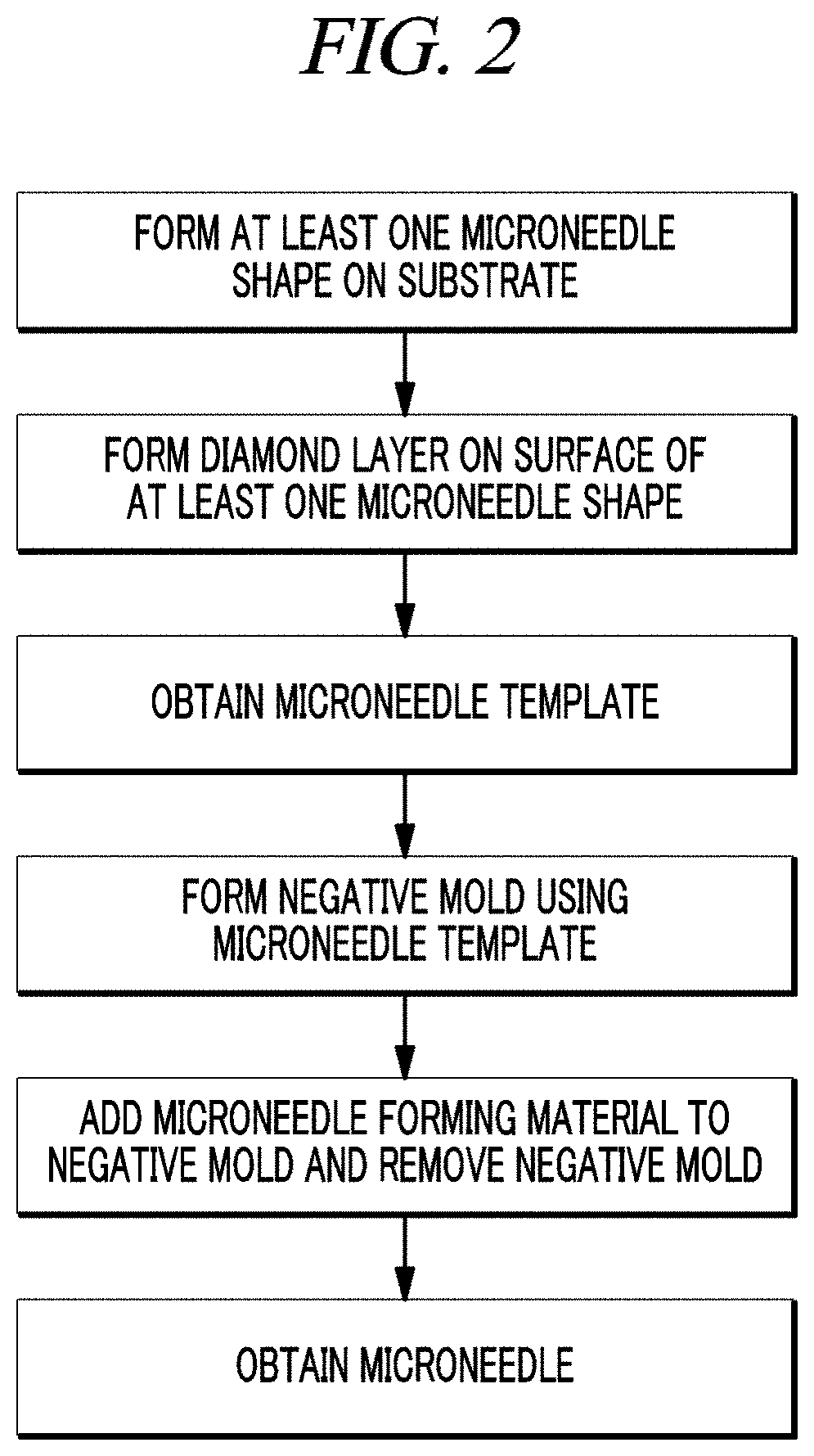
[0119]The microneedle template according to Example 1 was applied with PDMS or silicone or immersed in PDMS or silicone to form a negative mold.

[0120]The negative mold was applied with a mixture of 5% hyaluronic acid MMW, 3% hyaluronic acid oligomer, 0.5% trehalose, and 1% collagen without blisters.

[0121]Then, the mixture was dried at 50° C. for 3 hours to form a microneedle, and the microneedle was separated from the negative mold.

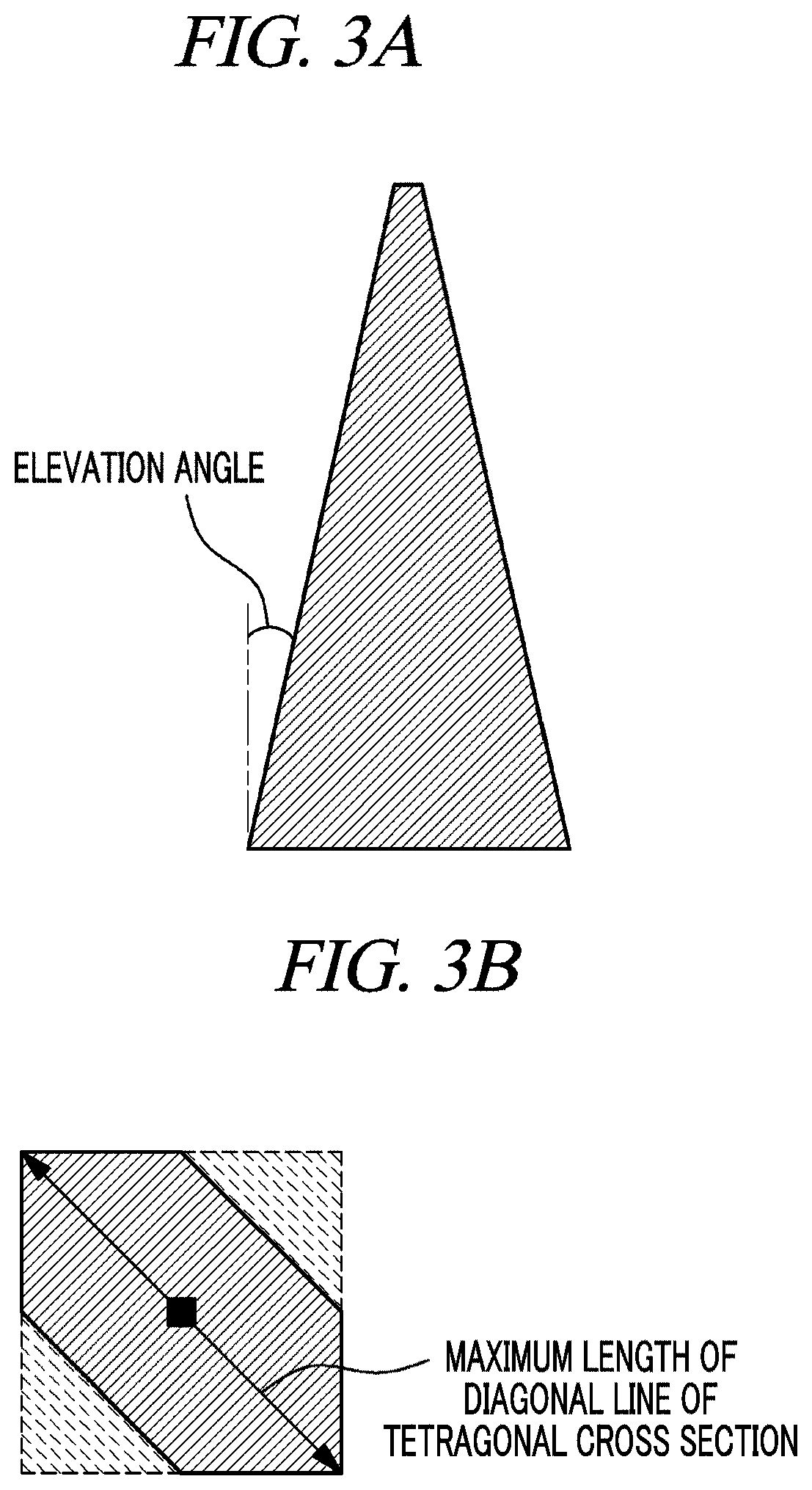
[0122]The shape of the obtained microneedle was as shown in FIGS. 7A and 7B. A ratio of the length of a portion having a hexagonal cross section to the length of a portion having a tetragonal cross section of the microneedle was measured at 1:1, and a ratio of the maximum length (67 μm) of a diagonal line of the tetragonal cross section to the maximum length (351 μm) of a diagonal line of the hexagonal cross section was measured at 1:5.23.


PUM

PropertyMeasurementUnit
thicknessaaaaaaaaaa
lengthaaaaaaaaaa
melting pointaaaaaaaaaa

Abstract

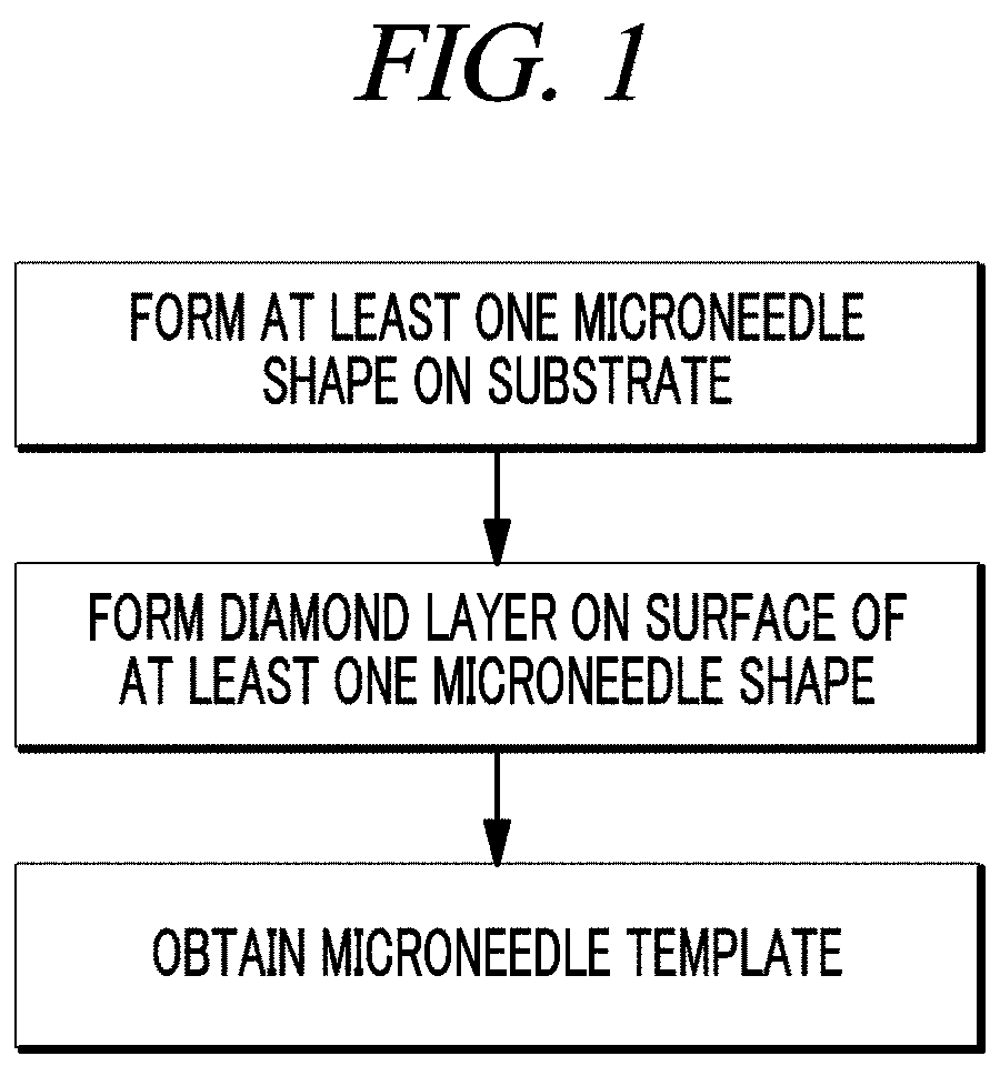
Provided are a microneedle template including: a substrate on which at least one microneedle shapes are formed; and a diamond layer formed on the surface of the at least one microneedle shapes, a method for preparing the microneedle template, a microneedle prepared using the microneedle template, and a method for preparing the microneedle.

Description

CROSS-REFERENCE TO RELATED APPLICATIONS[0001]This application is a continuation of PCT Application No. PCT / KR2018 / 001421, filed on Feb. 2, 2018, which claims priority to Korean Patent Application No. 10-2017-0115302, filed on Sep. 8, 2017, both of which are hereby incorporated by references in their entirety.TECHNICAL FIELD[0002]The present disclosure relates to a microneedle template including: a substrate on which at least one microneedle shapes is formed; and a diamond layer formed on the surface of the at least one microneedle shapes, a method for preparing the microneedle template, a microneedle prepared using the microneedle template, and a method for preparing the microneedle.BACKGROUND[0003]A drug delivery system (DDS) refers to a series of techniques for controlling the delivery of materials having pharmacological activity to cells, tissues, and organs using various physicochemical techniques. The most common drug delivery system is an oral drug intake. In addition, there i...

Claims


Application Information

Patent Timeline
Patent Type & Authority Patents(United States)
IPC IPC(8): A61M37/00B29C33/38A61B5/15B29L31/00
CPCA61M37/0015B29C33/3842A61B5/150984A61M2037/0023A61M2037/0046A61M2037/0053A61M2207/10B29K2907/045B29K2909/04B29L2031/756B29L2031/7544A61B5/150022A61B5/150282A61B5/150427A61B5/150435B29C33/38
Inventor LEE, JEONG GUNCHO, SHIN HEESHIN, BO YOUNG
Owner S SKIN CO LTD
Learn More