Carrier system for micro-optical and/or other functional elements of microtechnology

a carrier system and micro-optical technology, applied in the field of carrier systems for micro-optical and/or other functional elements of microtechnology, can solve the problems of not being able to adapt easily to other applications, not being able to produce retaining elements with current microsystem equipment, and not being able to meet general use, etc., to achieve high precision, reduce manufacturing costs, and be economical.

Inactive Publication Date: 2016-07-14
FRAUNHOFER GESELLSCHAFT ZUR FOERDERUNG DER ANGEWANDTEN FORSCHUNG EV +1
View PDF2 Cites 0 Cited by
  • Summary
  • Abstract
  • Description
  • Claims
  • Application Information

AI Technical Summary

Benefits of technology

[0024]The suggested carrier system particularly enables the implementation of a highly precise, economical, large format layout technology for manufacturing multilayer packaging (AVT) made of glass with subsequent depanelisation. Accordingly, 2.5D micro-optical benches, substrates that have been functionalised (mechanically, optically, fluidically, electrically, with regard to thermal conductivity) or also modular microsystem technology (MST) can be realised. The concept according to the invention for constructing the carrier system enables a heterogeneous system integration of different functional elements, for example the production of micro-optical benches for dynamic, highly precise positioning in six degrees of freedom on extremely planar substrates. The suggested carrier system then makes it possible for the coefficient of thermal expansion to be adapted. The carrier system further makes it possible to reduce costs in manufacturing through the use of commercially available heat-polished float or pulled glass panes or films (draw-down method), with naturally very low thickness tolerances and high evenness. It follows that no further cost intensive polishing steps are necessary, such as are required with metal substrates. Fully automatic assembly is also possible for creating the carrier system. The use of optically transparent glass materials means that no shadowing occurs when UV bonds are created or laser bonding is used to connect individual plates or components.

Problems solved by technology

However, the previously known solutions have always been highly application-specific and specialised, and they therefore do not lend themselves to general use, nor can they be adapted easily to other applications.
However, it has not yet proven possible with current microsystem equipment to produce retaining elements for micro-optical and / or other microtechnical functional elements from glass that are small enough, with a size in the range from a few μm to a few mm, and in the necessary shapes for the retaining function.
Techniques such as 3D printing and subsequent sintering processes or glass etching processes do not deliver the precision that is essential for many applications.
On the other hand, the functional elements are often not manufactured with sufficient precision, particularly in the case of inexpensive products, and must be aligned extremely precisely and accurately in as many as six degrees of freedom.

Method used


Image

  • Carrier system for micro-optical and/or other functional elements of microtechnology
  • Carrier system for micro-optical and/or other functional elements of microtechnology
  • Carrier system for micro-optical and/or other functional elements of microtechnology

Examples


Embodiment Construction

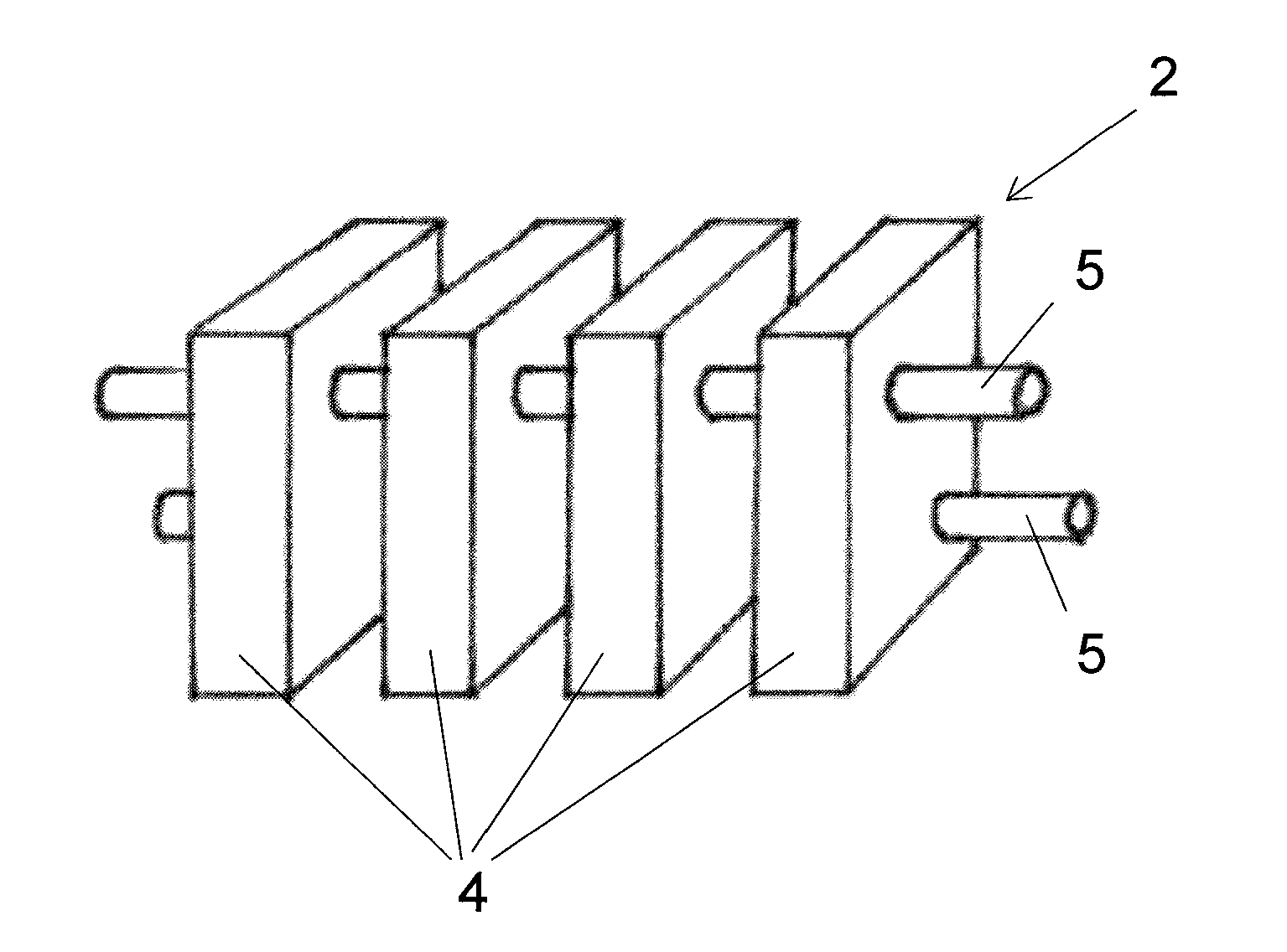
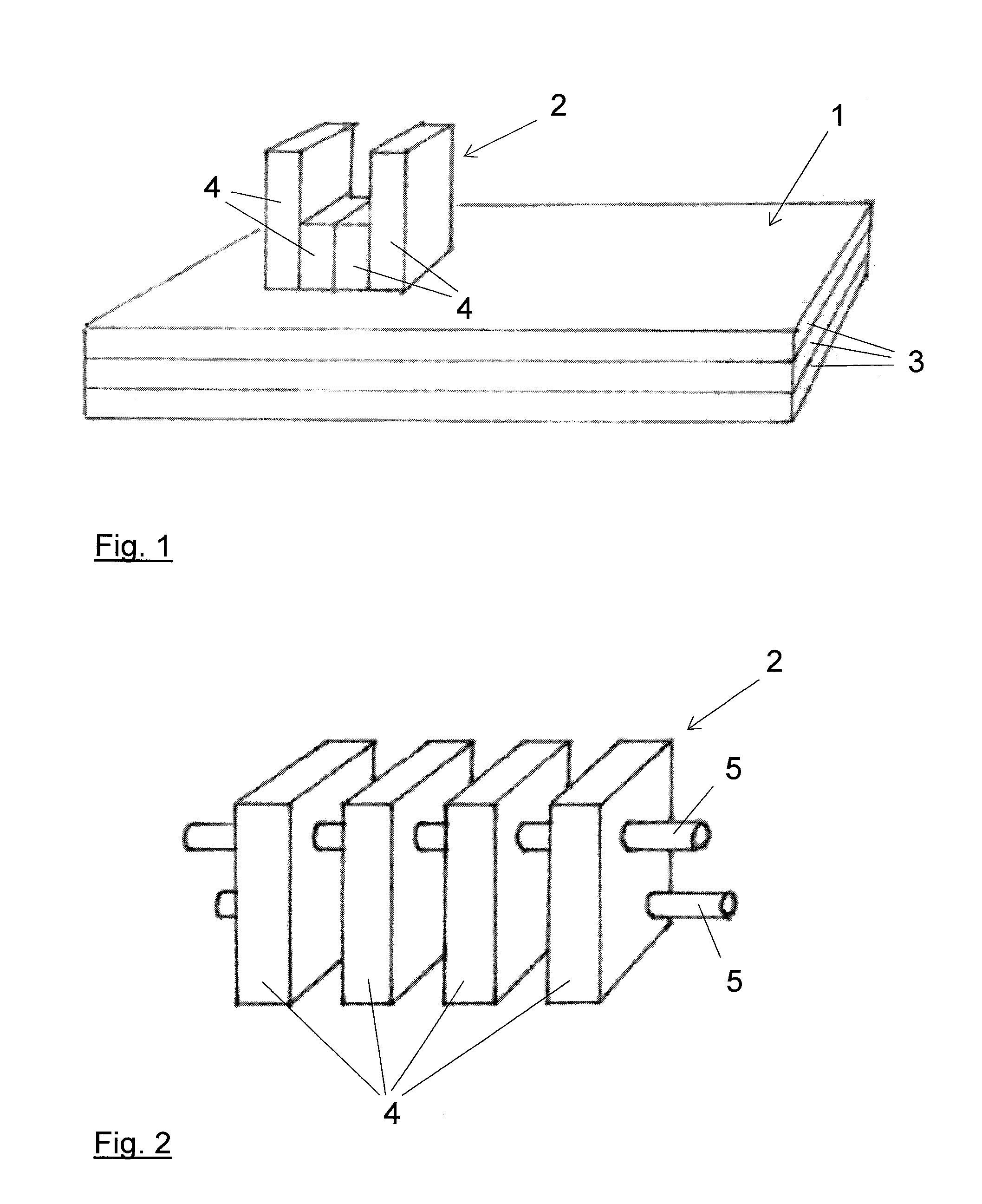
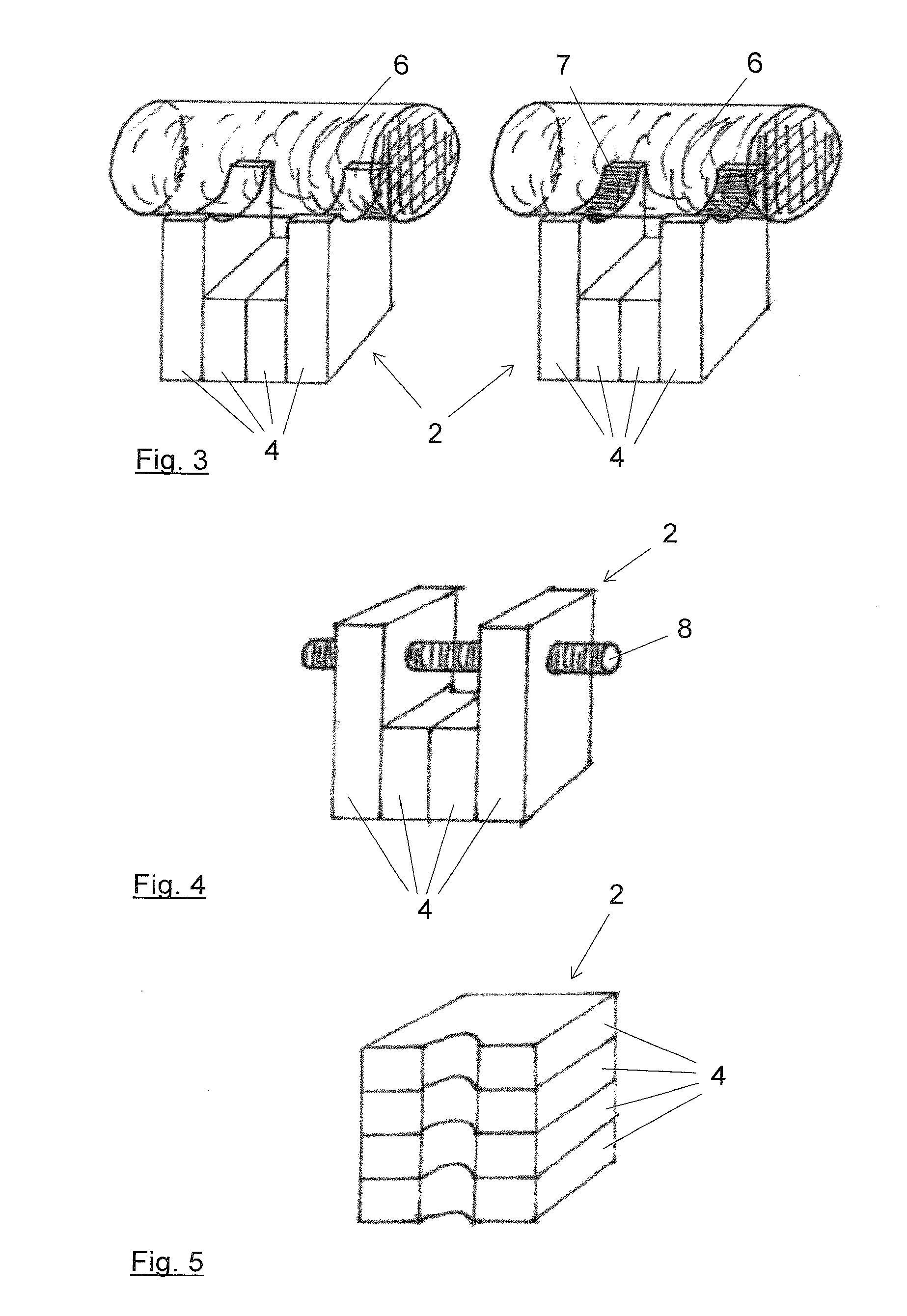
[0032]The proposed carrier system has a base plate and one or more retaining elements for the functional elements. At least some of the retaining elements are constructed from a plurality of thin stacked plates. In this regard, FIG. 1 shows a simplified representation of an example of such a carrier system, which in this example comprises only base plate 1 with a retaining element 2 fixed on top thereof. In this example, base plate 1 is also constructed from a plurality of stacked thin plates 3, as may be seen in the figure. Retaining element 2 in this example is constructed from vertically stacked thin plates 4, of which the two outer plates are higher than the two inner plates. Fastening of plates 4 to each other may be assured with glass-glass bonding, for example, when glass plates are used. Retaining element 2 may be secured on base plate 1 by a bonding technique, for example. As a rule, in most applications several retaining elements 2 constructed either identically or differe...


PUM


Abstract

The present invention relates to a carrier system for micro-optical and/or other functional elements of microtechnology, including a base plate and one or more retaining elements for the functional elements that are secured on the base plate. The suggested carrier system is characterized by the fact that the retaining elements are constructed partly or entirely from multiple thin, stacked plates that have a plate thickness of less than 1 mm. In this way, retaining elements for example made from glass or glass ceramic may be created extremely precisely in practically any geometrical shape.

Description

TECHNICAL FIELD[0001]The present invention relates to a carrier system for micro-optical and / or other functional elements of microtechnology, including a base plate and one or more retaining elements for the functional elements that are secured on the base plate.[0002]If optoelectronic components in particular, such as semiconductor lasers, photodiodes or modulators with micro-optical components such as microlenses, gratings and prisms, and connecting elements, such as optical fibres, for example, are arranged in hybrid manner on a platform, this is called a micro-optical bench. As with a macro-optical bench, these functional elements must be aligned, so special retaining elements have to be provided that are capable of compensating for different heights or angular settings, or which themselves serve as alignment aids for the functional elements.PRIOR ART[0003]In the past, carrier systems of such kind were created using an enormous variety of materials and techniques. However, the p...

Claims


Application Information

Patent Timeline
Patent Type & Authority Applications(United States)
IPC IPC(8): G02B6/36
CPCG02B6/3648G02B7/00G02B7/003
Inventor SCHROEDER, HENNINGARNDT-STAUFENBIEL, NORBERTMARX, SEBASTIANBOETTGER, GUNNAR
Owner FRAUNHOFER GESELLSCHAFT ZUR FOERDERUNG DER ANGEWANDTEN FORSCHUNG EV
Why Eureka
Try Eureka