
Bicycle parking stand for locking a bicycle to the stand comprising an electronic lock

a technology for parking stands and bicycles, applied in the direction of bicycle stands, anti-theft cycle devices, cycle equipment, etc., can solve the problems of bicycle theft, wire or u-lock, and the inconvenience of having to bring a heavy and costly chain,

Active Publication Date: 2022-08-02
JFS PATENTS APS
View PDF19 Cites 3 Cited by
  • Summary
  • Abstract
  • Description
  • Claims
  • Application Information

AI Technical Summary

Benefits of technology

[0015]Present invention relates to an electronic bicycle parking stand. It is the primary objective to deliver a bicycle stand where the cyclist does not have to use an external lock like a chain, wire or U-lock. It is another important objective to deliver a bicycle stand where professional power cutting tools, and not only a bolt cutter, is needed to steal the bicycle from the stand. It is a third objective to deliver a bicycle stand with leaning support of the bicycle that does not damage the bicycle in any way.
[0016]It is a fourth objective to deliver a bicycle stand that is easy and intuitive to use enabling the cyclist to park the bicycle fast and conveniently. Finally, it is another objective to provide a low cost and minimalist design with minimum installation costs.

Problems solved by technology

First one being bicycle theft because of chain, wire and U-locks not capable to withstand a bolt cutter.
Second disadvantage is the inconvenience of having to bring a heavy and costly chain, wire or U-lock.
Third major disadvantage is potential damage of the bicycle, especially damage of the front wheel and scratches of the frame.
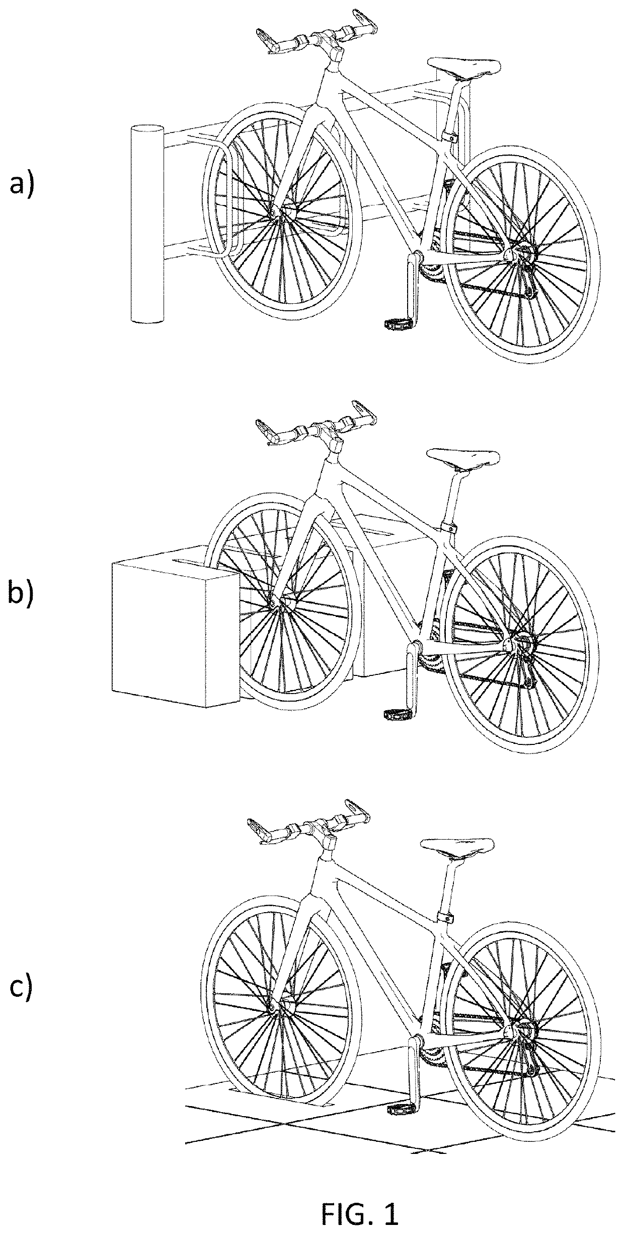
Damage of the front wheel is related to the far dominant prior art stand, which supports the bicycle by its front wheel. FIG. 1 shows 3 embodiments of this type and the damage happens if the bicycle is pushed over by the wind or a fellow cyclist.
These locking methods are subject to theft with a bolt cutter, and there is as well a high risk that the bicycle is scratched since most embodiments are plain metal.
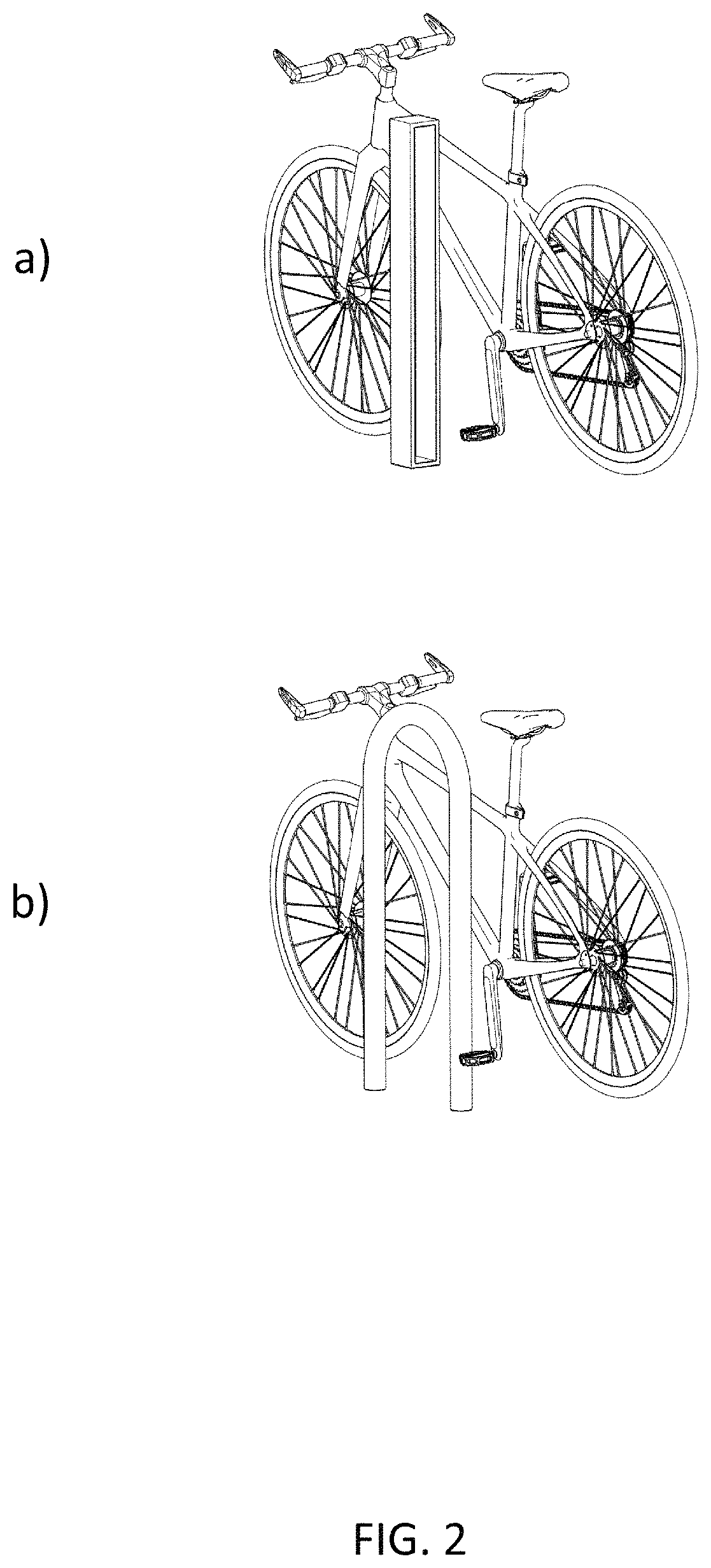
The far majority of prior art bicycle stands are the embodiments illustrated in FIG. 1 and FIG. 2 and the common problems for these are bicycle theft and the inconvenience of the cyclist having to bring a chain, wire or U-lock in order to lock the bicycle to the stand.
Majority of the locks sold can't withstand a bolt cutter, and those that can, are expensive, big and heavy.
Seen in a wider perspective bicycle theft is thereby negatively affecting the environment, the general health of the public and adds to the increasing problems of traffic jams in the cities.
Secondly, it doesn't offer the same level of theft protection and user convenience.
Locking system of EP0147384 is based on an external lock (chain, wire or U-lock) with the related risk of theft and secondly the cost and inconvenience of having to bring such a locking device.
Locking process of EP0147384 is as well rather inconvenient because of the complexity and low position of the locking process.
First one being that bicycle is leaned against the metal pole of the stand or the metal bar, whereby there is a risk that the bicycle gets scratched.
Second disadvantage is the fact that the locking metal bar must come through the front wheel, why the cyclist in many cases has to turn the front wheel to avoid the metal bar hitting a spoke.

Method used


Image

  • Bicycle parking stand for locking a bicycle to the stand comprising an electronic lock
  • Bicycle parking stand for locking a bicycle to the stand comprising an electronic lock
  • Bicycle parking stand for locking a bicycle to the stand comprising an electronic lock

Examples


Embodiment Construction

[0095]FIG. 4 through FIG. 19 illustrates present invention. FIG. 4 through FIG. 10 presents one embodiment and FIG. 11 through FIG. 17 presents another embodiment. FIG. 18 and FIG. 19 illustrates present innovation utilized in parking lot solutions.

[0096]FIG. 4 illustrates one embodiment of present invention in open mode ready for a bicycle to be parked. Open mode achieved by gate (E) and comprised striker-plate (F) turned through hinges (D) to a position where gate (E) is parallel to side wall (20) of said bottom section (A). Figure shows vertical side walls (10) and (20) and back wall (30) of bottom section (A) which directly or through a base is affixed to the ground or pavement. Figure also shows fender (L) fixed to the top front corner of side wall (10) and fender (K) also fixed to said side wall (10) but below fender (L).

[0097]Figure further shows top section (B) and comprised fender (M) fixed to the flexible section (40) of said top section (B). Flexibility of section (40) an...


PUM


Abstract

Present invention relates to a bicycle parking stand (1) for locking a bicycle to the stand (1). It comprises a bottom section (A) with a top section (B) fixed on top, a gate (E) hinged to bottom section (A) and top section (B) and an electronic unit (G) fixed inside top section (B). Electronic unit (G) comprises an electronic lock (H) with a latch (P) and a printed circuitry board (I) with an antenna placed underneath window (J) enabling operation of stand (1) by an electronic device. Stand (1) further comprises clamping means for releasable clamping a crankarm (V) to the clamping means. Gate (E) adapted to move from an open to a closed position where striker-plate (F) fixed to gate (E) engages latch (P) of the electronic lock (H) thereby preventing gate (E) from opening and the bicycle pulled out of the clamping means.

Description

CROSS-REFERENCE TO RELATED APPLICATIONS[0001]This is a 35 U.S.C. 371 National Stage Patent Application of International Application No. PCT / DK2020 / 050024, filed Jan. 28, 2020, which claims priority to Denmark application PA 2019 00163, filed Feb. 5, 2019, each of which is hereby incorporated by reference in its entirety.FIELD OF THE INVENTION[0002]A bicycle parking stand for locking a bicycle to the stand comprising:[0003]a bottom section directly or through a base affixed to the ground or pavement, said bottom section comprises a right vertical side wall, an opposite placed vertical left side wall and a back-wall.BACKGROUND OF THE INVENTION[0004]Prior art bicycle stands have 3 major disadvantages. First one being bicycle theft because of chain, wire and U-locks not capable to withstand a bolt cutter. Second disadvantage is the inconvenience of having to bring a heavy and costly chain, wire or U-lock. Third major disadvantage is potential damage of the bicycle, especially damage of ...

Claims


Application Information

Patent Timeline
Patent Type & Authority Patents(United States)
IPC IPC(8): B62H3/10B62H5/10B62H5/20
CPCB62H3/10B62H5/10B62H5/20B62H2700/005
Inventor SØRENSEN, JESPER FARVER
Owner JFS PATENTS APS
Learn More