Propulsion element including a catalyzing reactor

a technology of catalytic reactor and propellant element, which is applied in the direction of physical/chemical process catalyst, separation process, metal/metal-oxide/metal-hydroxide catalyst, etc., can solve the problem that the medium may not yet fully react via

Active Publication Date: 2022-08-23
NEDERLANDSE ORG VOOR TOEGEPAST NATUURWETENSCHAPPELIJK ONDERZOEK TNO
View PDF10 Cites 0 Cited by
  • Summary
  • Abstract
  • Description
  • Claims
  • Application Information

AI Technical Summary

Benefits of technology

[0007]An object of the invention is to provide a catalyzing reactor having an improved cold start performance. In particular, it is an object of the invention to provide a catalyzing reactor that can be operated without a external electrical heating element and / or does not require to be pre-pulsed. Additionally, a further object of the invention is to provide a catalyzing reactor which is relatively easy to model and reproduce.
[0031]The invention further relates to a use of a catalytic reactor as a propulsion element such as a thruster or an igniter for rocket engines with an improved cold start performance wherein a preheating element may not be required to warm the reactor sufficiently to be effective.

Problems solved by technology

However, in the upstream portion of the flow path, for example, near an inlet of the channel, the medium may not yet fully react via the catalyst because the desired operating temperature, wherein interaction of the catalyst with the medium may fully occur, has not yet been reached.

Method used


Image

  • Propulsion element including a catalyzing reactor
  • Propulsion element including a catalyzing reactor
  • Propulsion element including a catalyzing reactor

Examples


Embodiment Construction

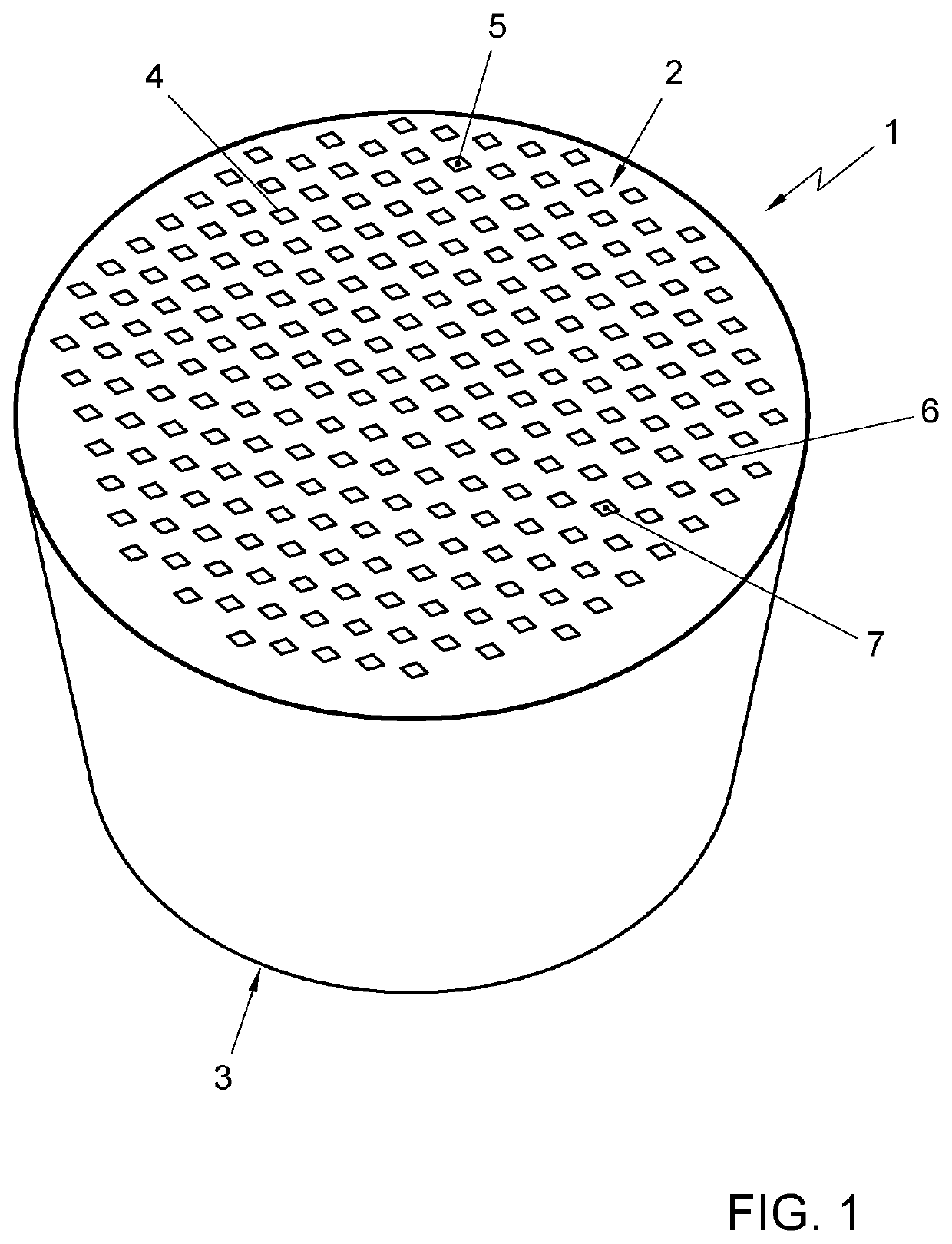
[0041]In FIG. 1 a catalyzing reactor 1 is shown. The reactor 1 is in this exemplary embodiment shown as a cylinder. However, other shapes are also possible such as a triangle, ellipsoid or rectangular. The reactor 1 may have a reactor entrance 2 and a reactor exit 3 and an internal structure 4 wherein a reacting medium can flow through the reactor 1 from the reactor entrance 2 to the reactor exit 3. The reactor structure 4 may comprise at least one reactor channel 5 with a relative thin channel wall 6 in comparison with the diameter, minimum width and / or minimum length of the reactor channel 5. Preferably, as shown in FIG. 1, the internal structure 4 may, for example, be designed as a honeycomb structure with a bundle of thin-walled heat conducting channels 5. The channels 5 can be arranged between the entrance 2 and the exit 3 of the reactor 1. The channels 5 may have a channel wall 6 that is made from a catalytic material or a non-catalytic support material and then coated with a ...


PUM

PropertyMeasurementUnit
temperatureaaaaaaaaaa
thicknessaaaaaaaaaa
angleaaaaaaaaaa

Abstract

A propulsion element including a catalyzing reactor is disclosed. The catalyzing reactor comprises a reactor entrance and a reactor exit and an internal structure arranged for flowing a reacting medium through the reactor from the reactor entrance to the reactor exit. The reactor structure comprising at least one thin walled reactor channel arranged between the entrance and the exit of the reactor. The channel having a channel wall that includes a catalyst and that defines a flow path, in which channel in use, a catalyzed exothermic reaction takes place in the medium as it flows along the flow path. The at least one channel is looped to have a portion of its flow path that is downstream with respect to the reactor entrance in heat exchanging contact with a portion of a flow path that is that is more upstream with respect to the reactor entrance, so as to transfer heat between a downstream portion of the reacting medium to an upstream portion thereof.

Description

CROSS-REFERENCE TO RELATED APPLICATIONS[0001]This application is a divisional of U.S. application Ser. No. 15 / 329,819, filed Jan. 27, 2017, which is a U.S. National Stage application under 35 U.S.C. § 371 of International Application PCT / NL2015 / 050547 (published as WO 2016 / 018146 A1), filed Jul. 24, 2015, which claims the benefit of priority to EP 14178972.7, filed Jul. 29, 2014. Each of these prior applications is hereby incorporated by reference in its entirety.FIELD OF THE INVENTION[0002]Embodiments of the invention relate to a propulsion element including a catalyzing reactor, in particular a fixed bed catalyzing reactor, a method for producing such a reactor and a use of a reactor.DESCRIPTION OF RELATED ART[0003]Catalyzing reactors are generally known and are e.g. used to control vehicle exhaust emissions or as thrusters in space propulsion. When configured as a so called fixed bed catalyzing reactor, these reactors usually comprise a reactor entrance and a reactor exit and an ...

Claims


Application Information

Patent Timeline
Patent Type & Authority Patents(United States)
IPC IPC(8): B01J19/24B01J19/00B01D53/94B01J23/50B01J35/04F01N3/24F02K9/95
CPCB01J19/2485B01D53/94B01J19/0013B01J19/243B01J23/50B01J35/04F01N3/24F02K9/95B01D2255/90B01J2219/00159B01J2219/2402B01J2219/2403B01J2219/2406B01J2219/2409B01J2219/2413B01J2219/2428F05D2220/80
Inventor VAN VLIET, LAURENS DANIËLSTRAATHOF, MICHIEL HANNESVAN DER WERFF, JEICHIENUS JOHANNES
Owner NEDERLANDSE ORG VOOR TOEGEPAST NATUURWETENSCHAPPELIJK ONDERZOEK TNO
Why Eureka
Try Eureka