
Stationary phase for solid-phase microextraction device

a microextraction device and stationary phase technology, applied in the direction of instruments, other chemical processes, separation processes, etc., can solve the problems of affecting the extractive efficiency or uniformity of the coating, presenting functionalization and adhesion problems, and lack of intrinsic reproducibility, so as to achieve better extractive efficiencies

Active Publication Date: 2022-09-06
UNIV DE LA LAGUNA - OTRI
View PDF10 Cites 0 Cited by
  • Summary
  • Abstract
  • Description
  • Claims
  • Application Information

AI Technical Summary

Benefits of technology

[0017]The synthesis of the stationary phase is simple, does not require numerous steps and is environmentally sustainable, since it does not use organic solvents (see first preferred embodiment of the invention), unlike other stationary phases previously described. In addition, the synthesis does not require additional materials such as polymers, ionic liquids or carbon nanomaterials acting as a support, adjuvant or support to bind the MOF to the substrate and that can affect the extractive efficiency or the uniformity of the coating and, particularly, substantial differences between consecutive syntheses (with the consequent lack of intrinsic reproducibility).
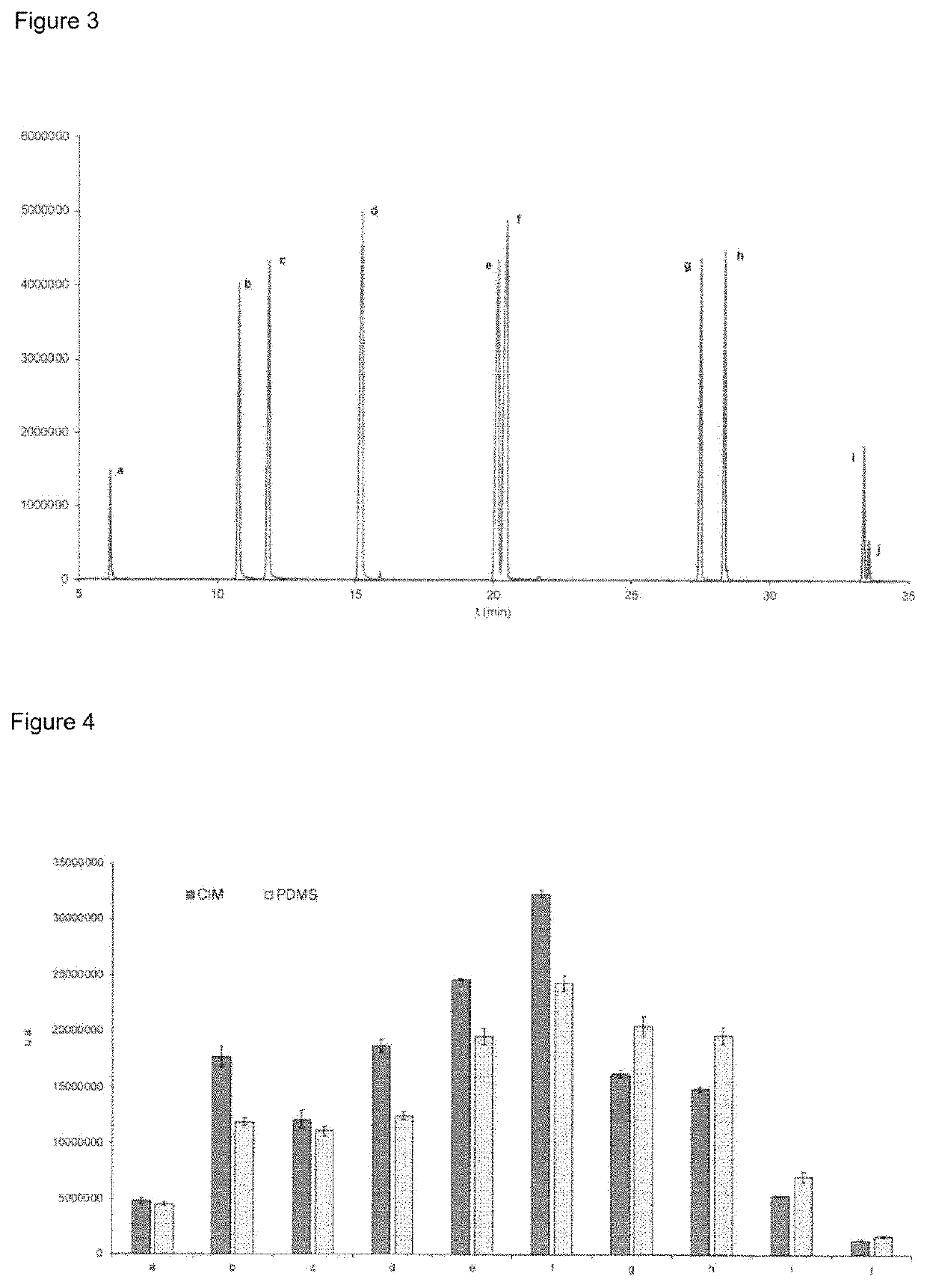
[0018]The stationary phase SPME device described in this invention can be used for the determination of polycyclic aromatic hydrocarbons in water and better extractive efficiencies are obtained compared to those obtained with commercial fibers available under identical conditions.

Problems solved by technology

Nickel / titanium alloys had been previously tested presenting functionalization and adhesion problems due to the coating falling off (peeling-off).
In addition, the synthesis does not require additional materials such as polymers, ionic liquids or carbon nanomaterials acting as a support, adjuvant or support to bind the MOF to the substrate and that can affect the extractive efficiency or the uniformity of the coating and, particularly, substantial differences between consecutive syntheses (with the consequent lack of intrinsic reproducibility).

Method used


Image

  • Stationary phase for solid-phase microextraction device
  • Stationary phase for solid-phase microextraction device

Examples


Embodiment Construction

[0028]The following examples are provided by way of illustration and are not intended to limit the present invention.

[0029]In one embodiment of the invention, the stationary phase of the radial atomic sequence Ni / Ti—O—Si—CH2—(CH2)4—CH2—NH2—Al—O—C-metal-organic framework (MOF) is obtained by means of three steps: i) immersion of the nucleus in an alkaline solution, ii) adhesion of a silane with amino-terminal functionalization and iii) growth of the MOF by means of a solvothermal technique. The detailed method is as follows:

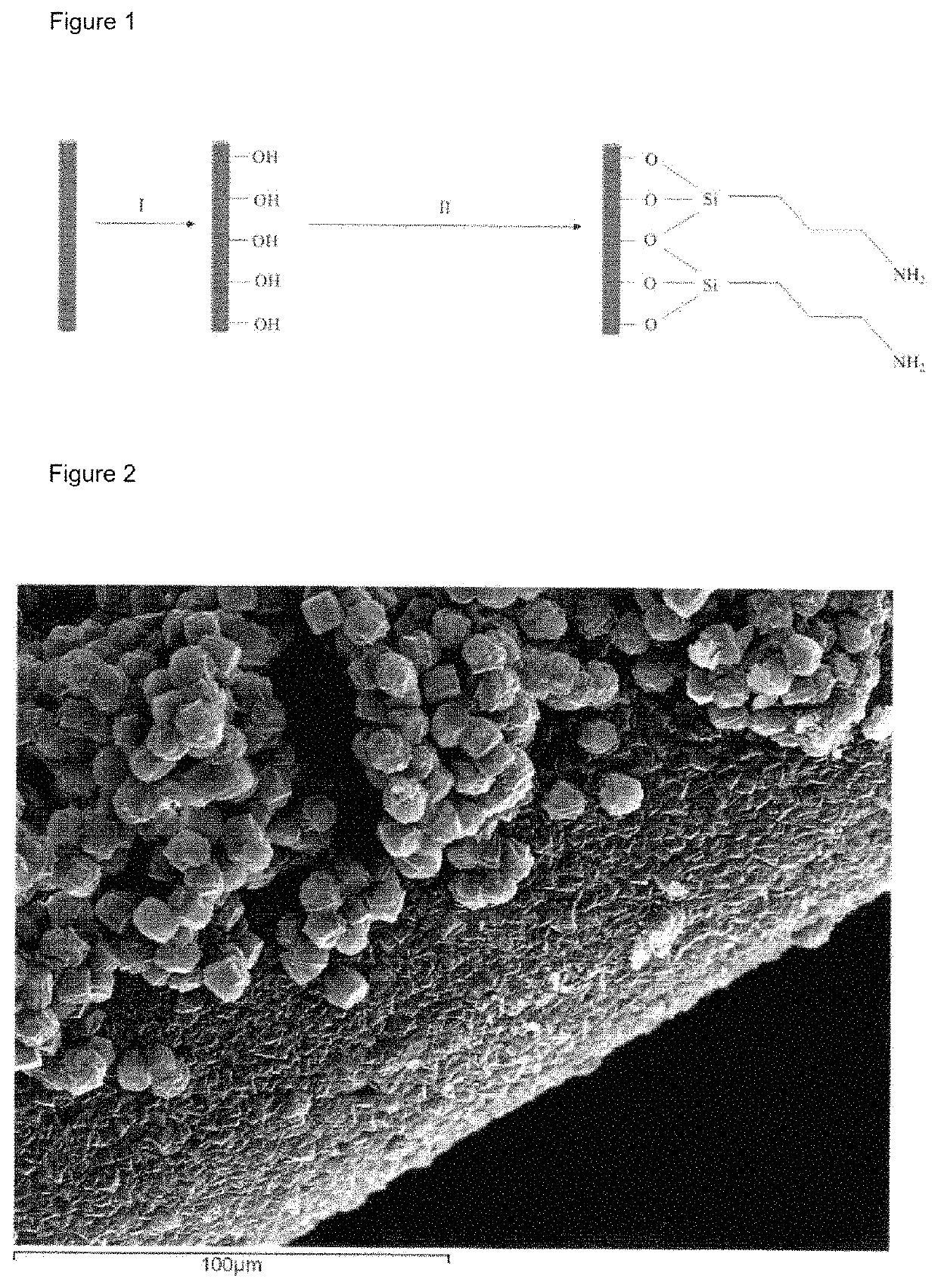
[0030]1. A nitinol fiber is used and immersed in a solution of H2O2 (5-30% v / v) for 1-3 hours at reflux. The fiber is extracted and washed with distilled water and ethanol. The fiber is then introduced into a vial containing (3-aminopropyl) triethoxysilane for 2-24 hours at 30-50° C. The fiber is extracted and washed with ethanol (FIG. 1).

[0031]2. 1 cm of the pretreated fiber is immersed in an aqueous solution (15 ml) containing 1 mmol of mesaconic acid, 1 mmol of...


PUM

PropertyMeasurementUnit
thicknessesaaaaaaaaaa

Abstract

The present invention provides a stationary phase for solid-phase microextraction (SPME) devices based on nickel and titanium alloy nuclei and a metal-organic framework (MOF) exterior, which may be used for chromatographic analysis in environmental, food, etc. applications. The method of preparation of the stationary phases consists of a number of steps which provide a covalent adhesion of the MOF to the nickel / titanium alloy. In these stationary phases, the metal-organic framework is the only component that comes into contact with the sample to be analysed. The interior of the stationary phase is executed in nitinol and endows the system with thermal and mechanical stability, this being the first time that it is used to support a metal-organic framework, and presenting extractive advantages in comparison with commercial SPME stationary phases.

Description

BACKGROUND OF THE INVENTION[0001]1. Field of the Invention[0002]The present invention is directed to contaminant monitoring devices. More particularly, the invention is directed to a stationary phase with metal-organic frameworks (MOF) for a solid-phase microextraction (SPME) system.[0003]2. Discussion of the Related Art[0004]Metal-organic frameworks are crystalline coordination polymers made up of an organic ligand (at least ditopic) and a metal ion or cluster of metal ions with a three-dimensional structure (ES2356130). These materials have permanent porosity and remain crystalline after the activation process wherein the guest molecules are dislodged, with thermal stability in the range of 150 to 200° C. They are characterized by their ease to be modified according to the properties sought.[0005]Solid-phase microextraction (SPME) is an analytical extraction and pre-concentration technique developed by Pawliszyn in 1989 (ES2056644). This technique consists of the use of a stainles...

Claims


Application Information

Patent Timeline
Patent Type & Authority Patents(United States)
IPC IPC(8): B01J20/22B01J20/28B01J20/02
CPCB01J20/226B01J20/0225B01J20/28023B01D15/3828B01J20/289B01J20/3204B01J20/3219B01J20/3236B01J20/3293B01J20/02B01J20/28002B01J20/3206
Inventor PASÁN GARCIA, JORGEPINO ESTÉVEZ, VÉRONICAAFONSO PERERA, ANA MA.AYALA DÍAZ, JUAN H.PACHECO FERNÁNDEZ, IDAIRABAUTISTA, PRISCILÍA ROCIO
Owner UNIV DE LA LAGUNA - OTRI
Learn More