Control device for machine tools and machine tool control method

a control device and tool technology, applied in the direction of program control, electric programme control, instruments, etc., can solve the problems of chip scraping, affecting the machining of workpieces, sticking to the cutting tool,

Active Publication Date: 2022-09-06
FANUC LTD
View PDF8 Cites 0 Cited by
  • Summary
  • Abstract
  • Description
  • Claims
  • Application Information

AI Technical Summary

Benefits of technology

[0009]According to the present invention, it is possible to perform oscillation cutting for which sawn lines are hardly noticeable.

Problems solved by technology

With such a machine tool such as a lathe, since the cutting edge of the cutting tool continuously scrapes off material of the surface of the workpiece, there is a possibility of (chips) the material scraped off becoming elongated shavings, and sticking to the cutting tool and inhibiting machining of the workpiece.

Method used


Image

  • Control device for machine tools and machine tool control method
  • Control device for machine tools and machine tool control method
  • Control device for machine tools and machine tool control method

Examples


first embodiment

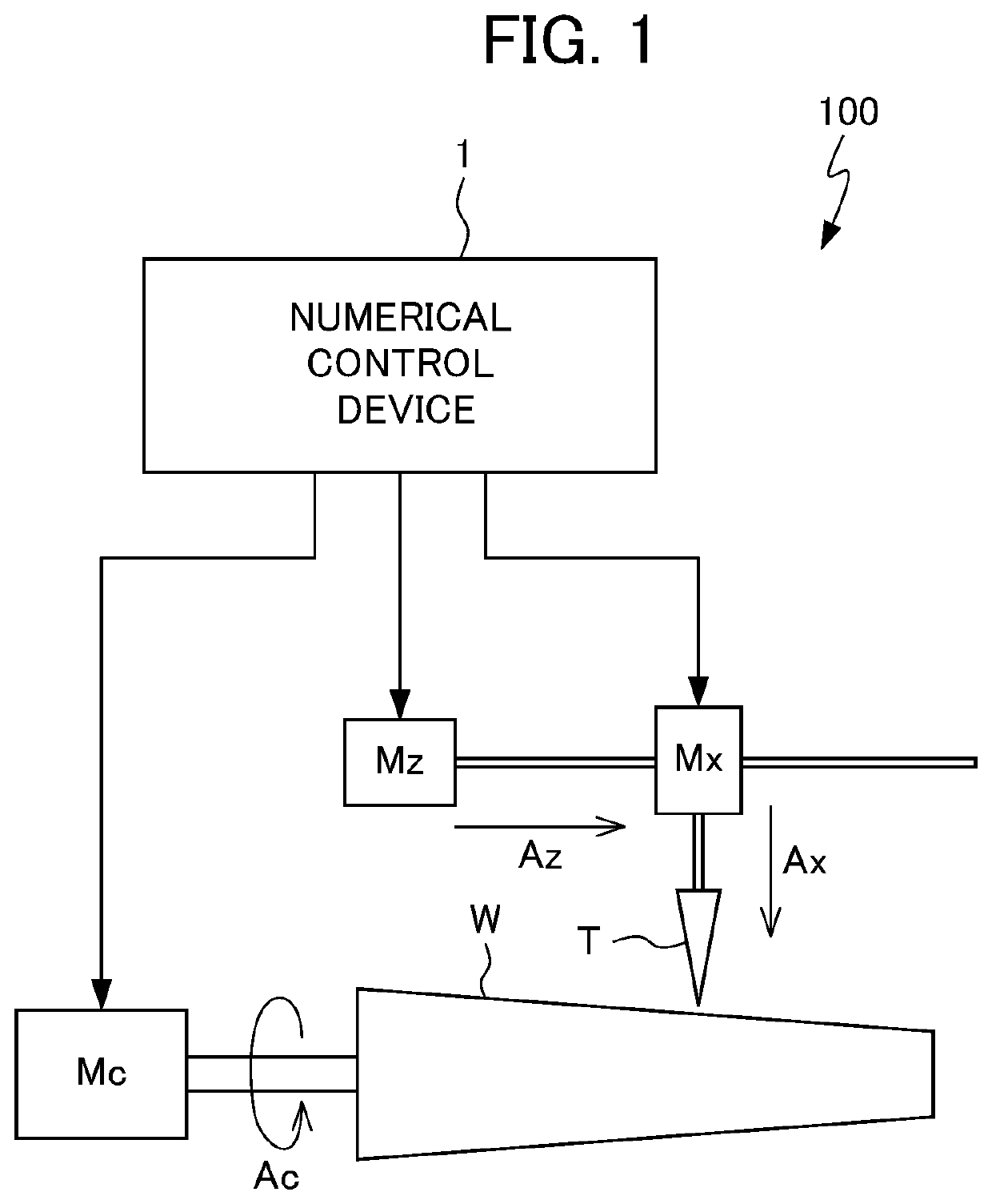
[0015]Hereinafter, an embodiment of the present disclosure will be explained while referencing the drawings. FIG. 1 is a schematic view showing the configuration of a machine tool 100 equipped with a numerical control device 1 which is a control device for machine tools according to the present disclosure.

[0016]The machine tool 100 is an NC lathe that cuts a workpiece W, which is a machining target using a cutting tool T. The machine tool 100 has the three drive axes of a spindle Ac that causes a cutting tool T or workpiece W to rotate (in the present embodiment, rotates the workpiece W); a feed axis Az that causes the cutting tool T to relatively move (in the present embodiment, moves the cutting tool T) in a direction parallel to the rotation axis of the spindle Ac relative to the workpiece W; and a cut-in axis Ax that causes the cutting tool T to relatively move (in the present embodiment, moves the cutting tool T) in the radial direction of the spindle Ac relative to the workpie...

second embodiment

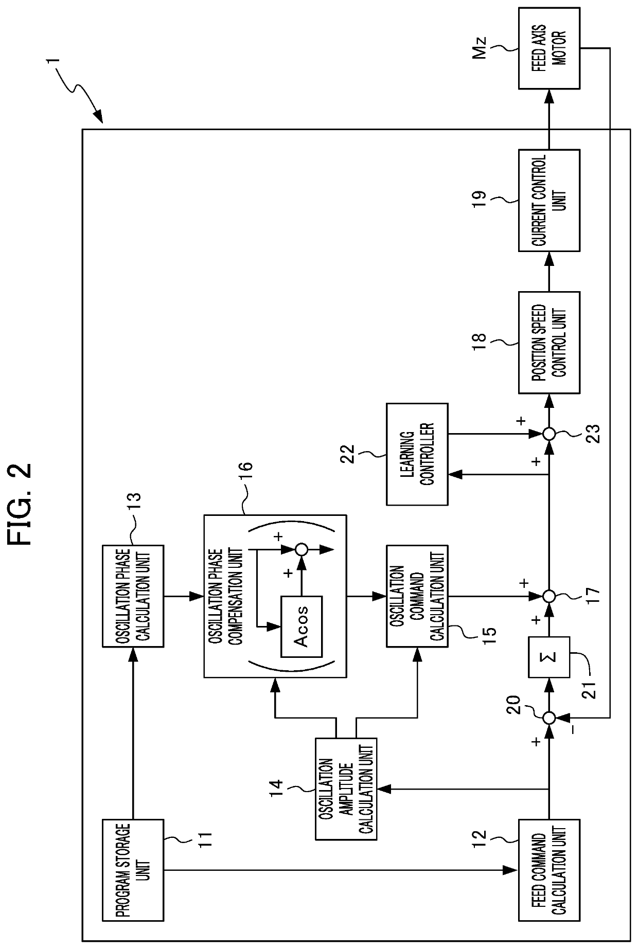
[0051]Next, FIG. 5 shows a numerical control device 1A which can be used in place of the numerical control device 1 of FIG. 2 in the machine tool 100 of FIG. 1. The numerical control device 1A of FIG. 5 is a numerical control device according to the present invention. For the numerical control device 1A of FIG. 5, the same reference symbols are assigned to constituent elements shared with the numerical control device 1 of FIG. 1, and redundant explanations may be omitted.

[0052]The numerical control device 1A includes: a program storage unit 11 which stores machining programs; a feed command calculation unit 12 which calculates a feed command causing the feed axis Az to move; a oscillation phase calculation unit 13 which calculates an oscillation phase that is a phase of oscillation of the feed axis Az based on the rotation number of the spindle Ac; an oscillation amplitude calculation unit 14 which calculates the amplitude of oscillation causing the feed axis to reciprocally move; a...


PUM


Abstract

A control device for machine tools according to an aspect of the present disclosure controls a machine tool which cuts the workpiece by way of the cutting tool by causing the spindle and the feed axis to cooperatively act, the control device including: a feed command calculation unit which calculates a feed command for causing the feed axis to relatively move in relation to the workpiece; an oscillation phase calculation unit which calculates an oscillation phase that is a phase of oscillation to cause the feed axis to reciprocally move based on a rotation number of the spindle; an oscillation phase compensation unit which compensates the oscillation phase; an oscillation amplitude calculation unit which calculates an oscillation amplitude that is an amplitude of oscillation causing the feed axis to reciprocally move based on the feed command; an oscillation command calculation unit which calculates an oscillation command causing the feed axis to reciprocally move, based on the oscillation amplitude and the oscillation phase after compensation by the oscillation phase compensation unit; and a command synthesizing unit which calculates a synthetic command for driving the feed axis by superimposing the feed command and the oscillation command.

Description

BACKGROUND OF THE INVENTION[0001]This application is based on and claims the benefit of priority from Japanese Patent Application No. 2019-226792, filed on 16 Dec. 2019, the content of which is incorporated herein by reference.FIELD OF THE INVENTION[0002]The present invention relates to a control device for machine tools, and a machine tool control method.RELATED ART[0003]Conventionally, machine tools such as lathes, for example, are being used which have a spindle that causes a cutting tool and a workpiece to relatively rotate, and a feed axis that causes the cutting tool and the workpiece to relatively move in a predetermined feed direction, and cuts the workpiece by way of the cutting tool by causing the spindle and feed axis to cooperatively act.[0004]With such a machine tool such as a lathe, since the cutting edge of the cutting tool continuously scrapes off material of the surface of the workpiece, there is a possibility of (chips) the material scraped off becoming elongated s...

Claims


Application Information

Patent Timeline
Patent Type & Authority Patents(United States)
IPC IPC(8): G05B19/416G05B19/404
CPCG05B19/4166G05B19/404G05B2219/37355G05B2219/49077G05B19/19G05B2219/45136G05B2219/45044G05B2219/49384
Inventor MORIHASHI, RYOUYAMAMOTO, KENTA
Owner FANUC LTD
Why Eureka
Try Eureka