Fuel pump unit

a technology of fuel pump and pump body, which is applied in the direction of filtration separation, electrical control, separation process, etc., can solve the problems of possible uneven transmission of vibration, etc., and achieve the effect of limiting the tilting of suction filter

Active Publication Date: 2022-09-13
DENSO CORP
View PDF21 Cites 1 Cited by
  • Summary
  • Abstract
  • Description
  • Claims
  • Application Information

AI Technical Summary

Benefits of technology

[0006]The present disclosure is made in view of the above disadvantage, and it is an objective of the present disclosure to provide a fuel pump unit that can limit tilting of a suction filter.
[0019]With the above construction, the columnar hole portion, which has the inner peripheral wall formed into the columnar hole form, communicates between the inside space of the filter element and the suction hole portion upon fitting of the inner peripheral wall to the outer peripheral wall that surrounds the suction hole portion in the fuel pump. The columnar hole portion is placed such that the rotational axis extends on the inner side of the inner peripheral wall. With the above construction, it is possible to limit tendency of transmitting vibrations, which would be generated at the fuel pump in response to the rotation of the rotatable shaft, to the specific location of the columnar hole portion. That is, a degree of uniformity in the transmission of the vibrations in the circumferential direction is increased, so that the tilting of the suction filter relative to the fuel pump can be limited.

Problems solved by technology

However, with this structure, vibrations, which would be generated at the fuel pump in response to rotation of the rotatable shaft, are likely transmitted to a specific location of the columnar hole portion.
That is, the transmission of the vibrations is not uniform.
Due to the non-uniform transmission of the vibrations, the suction filter may possibly be tilted relative to the fuel pump.

Method used


Image

  • Fuel pump unit
  • Fuel pump unit
  • Fuel pump unit

Examples


first embodiment

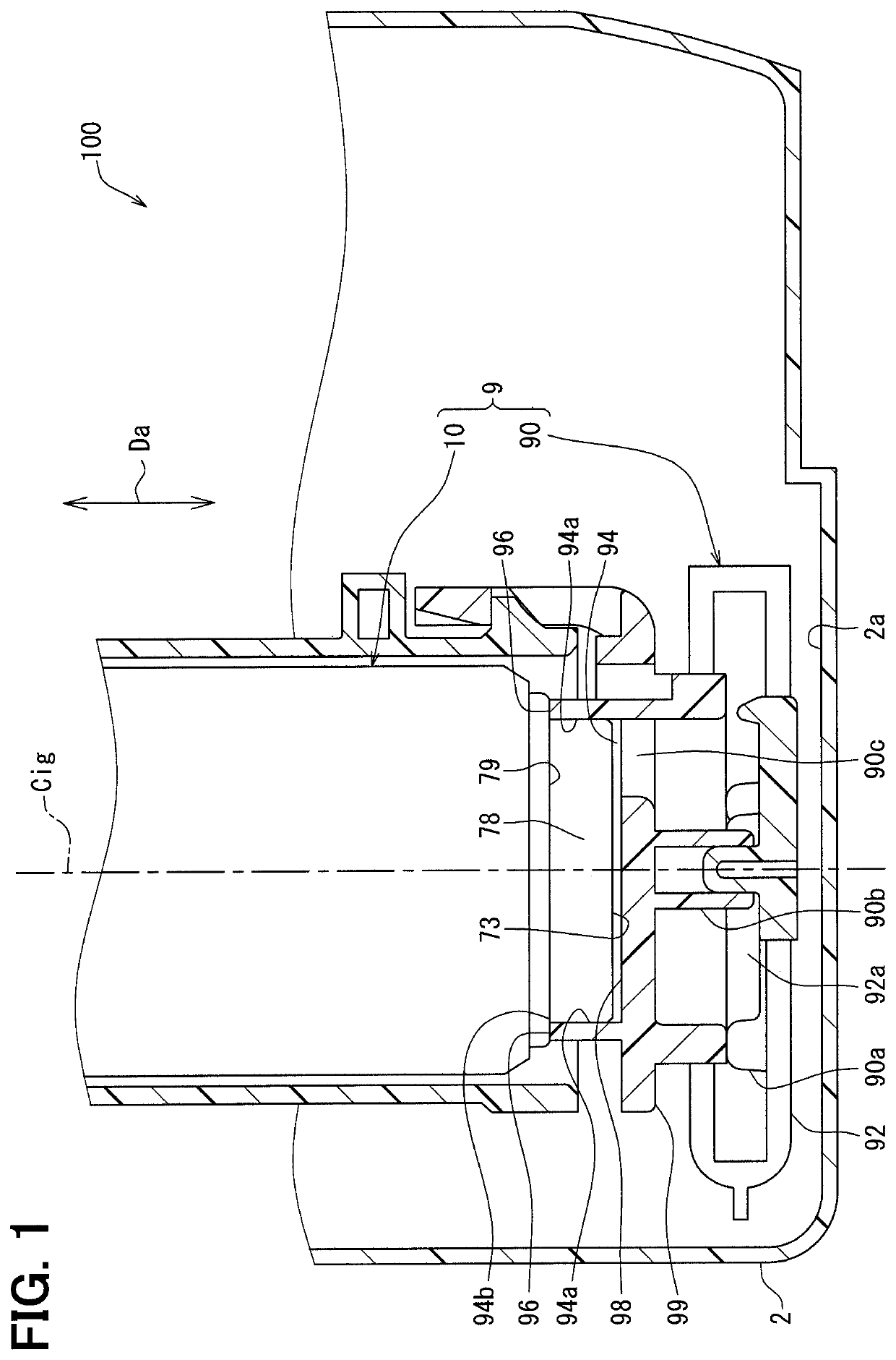
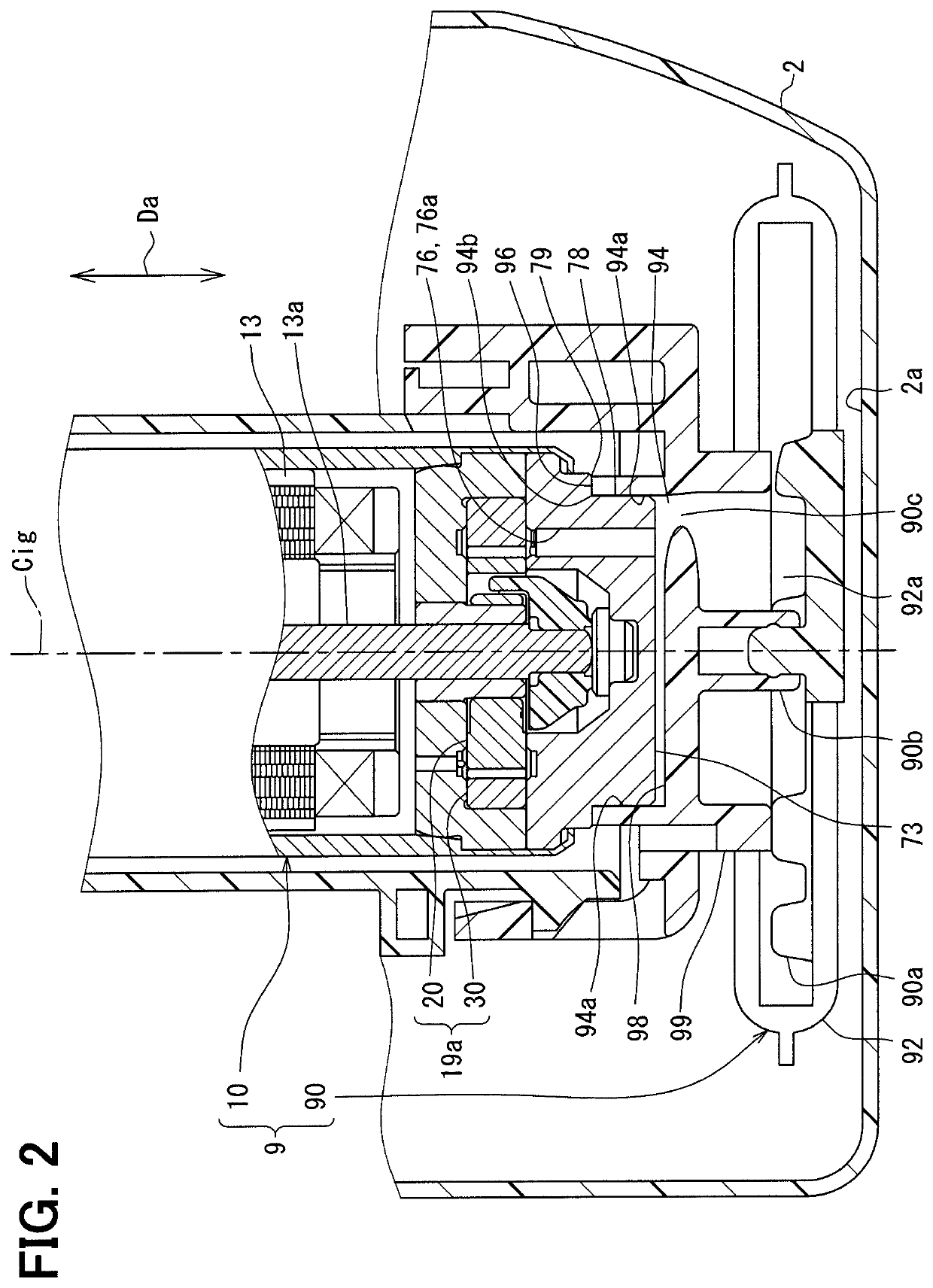
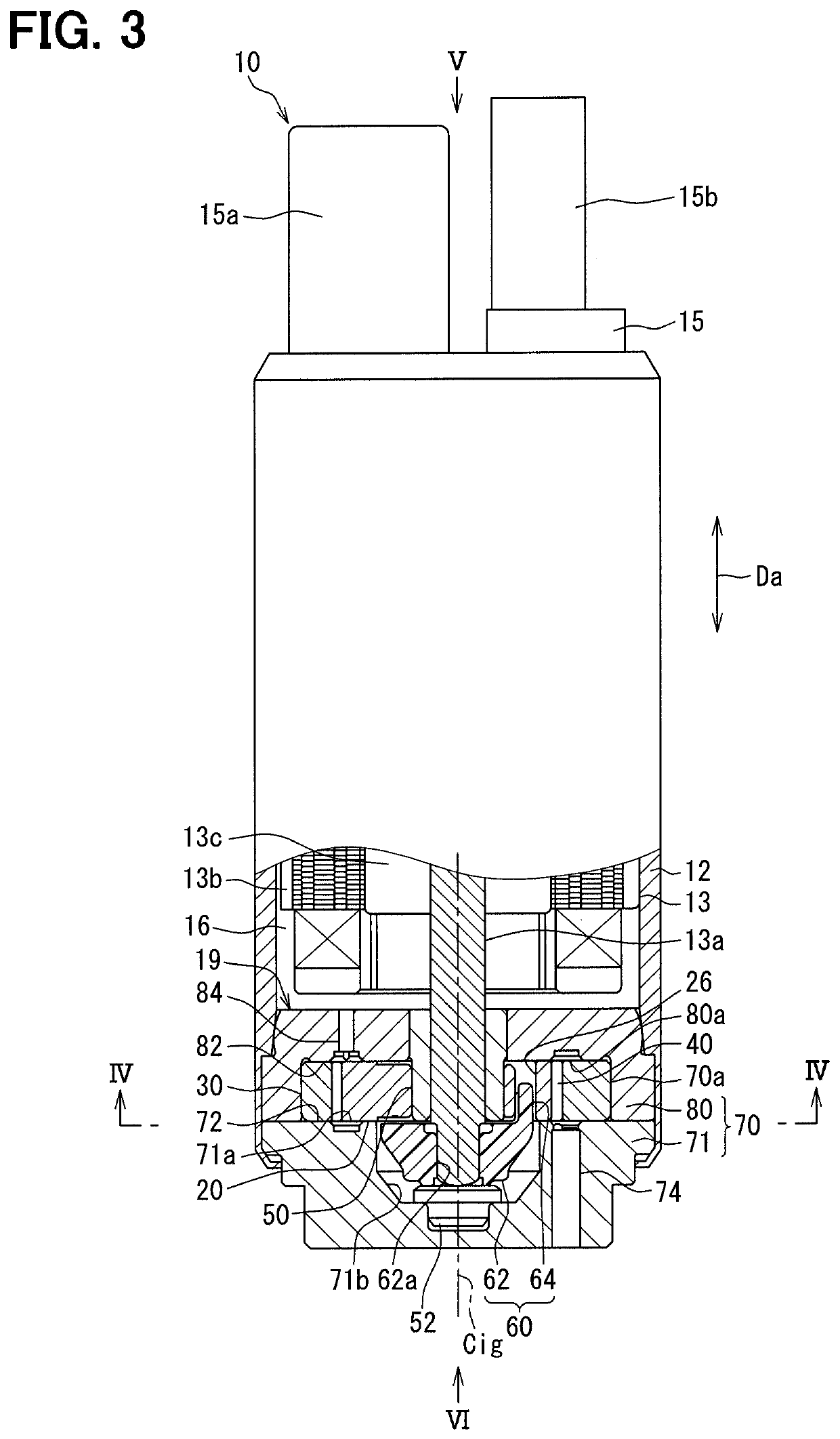
[0030]As shown in FIGS. 1 and 2, a fuel pump unit 9 according to a first embodiment of the present disclosure includes a suction filter 90 and a fuel pump 10, which are joined together. The fuel pump unit 9 is placed in a sub-tank 2 of a fuel pump module 100 that is installed in a fuel tank, which stores fuel, at a vehicle.

[0031]The fuel pump module 100 pumps the fuel of the fuel tank to an outside of the fuel tank to supply the fuel to an internal combustion engine. Although not shown in detail in the drawings, the fuel of the fuel tank is supplied into an inside of the sub-tank 2 through a flapper valve. The fuel in the sub-tank 2 is filtered through the suction filter 90 and is thereafter suctioned into the fuel pump 10. Thereafter, the fuel, which is discharged from the fuel pump 10, is conducted through a high pressure filter and a pressure regulator and is thereafter delivered to the outside of the fuel tank through a flange, which closes a fuel tank opening part at the fuel p...

second embodiment

[0075]As shown in FIG. 8, a second embodiment of the present disclosure is a modification of the first embodiment. The second embodiment will be mainly discussed with respect to differences, which are different from the first embodiment.

[0076]The fuel pump 10 of the second embodiment includes the opening planar surface 73, in which the suction hole portion 76 opens, like in the first embodiment.

[0077]Like in the first embodiment, the suction filter 290 of the second embodiment includes the opposing wall 98 that is opposed to the opening planar surface 73 in the axial direction Da. Unlike the first embodiment, the suction filter 290 further includes an elastic member 291.

[0078]The elastic member 291 is, for example, a rubber packing mainly made of a synthetic rubber and is shaped into a partially circular form having a thin wall. The elastic member 291 is elastically deformable. The elastic member 291 is placed between the opening planar surface 73 and the opposing wall 98 and can ex...


PUM

PropertyMeasurementUnit
Daaaaaaaaaaa
Daaaaaaaaaaa
pore sizeaaaaaaaaaa

Abstract

A fuel pump unit includes a suction filter and a fuel pump. The fuel pump includes: a rotatable shaft placed along a rotational axis; a rotor portion that rotates in response to rotation of the rotatable shaft; a suction hole portion, through which the fuel is suctioned into an inside of a rotor receiving chamber; and an outer peripheral wall that surrounds the suction hole portion. The suction filter includes: a filter element that filters the fuel and conducts the filtered fuel into an inside space; and a columnar hole portion having an inner peripheral wall, while the outer peripheral wall and the inner peripheral wall are fitted with each other, so that the columnar hole portion communicates between the inside space and the suction hole portion. The columnar hole portion is placed such that the rotational axis extends on an inner side of the inner peripheral wall.

Description

CROSS REFERENCE TO RELATED APPLICATION[0001]This application is the U.S. national phase of International Application No. PCT / JP2016 / 084871 filed Nov. 25, 2016 which designated the U.S. and claims priority to Japanese Patent Application No. 2015-246453 filed on Dec. 17, 2015, the entire contents of each of which are hereby incorporated by reference.TECHNICAL FIELD[0002]The present disclosure relates to a fuel pump unit that includes a suction filter and a fuel pump.BACKGROUND ART[0003]Previously, there is known a fuel pump unit that includes a suction filter and a fuel pump. In the fuel pump unit of the patent literature 1, the fuel pump suctions fuel, which is filtered through the suction filter. The fuel pump includes: a suction hole portion, through which fuel is suctioned into a rotor receiving chamber; and an outer peripheral wall, which surrounds the suction hole portion.[0004]The suction filter includes a filter element and a columnar hole portion. The filter element filters t...

Claims


Application Information

Patent Timeline
Patent Type & Authority Patents(United States)
IPC IPC(8): F02M37/02F02M37/44F02M37/10F02M37/50F04C2/10F02M37/04F04C13/00B01D35/027F04C15/06F02D41/30
CPCF02M37/02B01D35/027F02M37/045F02M37/10F02M37/106F02M37/44F02M37/50F04C2/102F04C13/005F04C13/008F02D41/3082F04C15/06F04C2210/203
Inventor HAYAKAWA, TETSUOSAKAI, HIROMIFURUHASHI, DAIJI
Owner DENSO CORP
Why Eureka
Try Eureka