Apparatus for the production of molded concrete parts in a molding machine

a technology of a molding machine and a molding plate, which is applied in the direction of ceramic molding apparatus, manufacturing tools, presses, etc., can solve the problems of pressure plate collision with the top side of the lower mold part, and the risk is particularly high, so as to prevent the damage of the pressure plate

Active Publication Date: 2017-04-04
KOBRA FORMEN
View PDF7 Cites 0 Cited by
  • Summary
  • Abstract
  • Description
  • Claims
  • Application Information

AI Technical Summary

Benefits of technology

[0010]If is the task of the invention to create an apparatus for the production of molded concrete parts in a molding machine, in which centering between upper mold part and lower mold part is further improved, particularly in order to prevent damage to pressure plates if they possibly make contact with side walls of the mold insert.
[0013]According to the invention, the lower mold part is therefore connected with the upper mold part not with a compulsory guide that merely would allow establishment of relative positions between upper mold part and lower mold part. It has surprisingly been shown that a guide means that allows tilting of the upper mold part from the vertical direction allows greater stability and longer useful lifetimes of the pressure plates attached to the pressure punch, because fine structures, in particular, such as indentations or chamfers on the pressure plates, demonstrate less wear. The solution according to the invention thereby does not attempt to focus on correct and centered installation of the lower mold part relative to the upper mold part, in order to be able to prevent the pressure plate from touching an opening of the mold, but rather makes it possible to keep effects low in the case of possible touching, by means of procurement of an additional degree of freedom in the movement of the pressure plates. In addition, a starting position for the location of the lower mold part relative to the upper mold part is created by means of the guidance of the lower mold part in the guide means, which position can result in contact-free introduction of the pressure plates. Instead of predetermining the precise relative positioning, which is furthermore rigidly predetermined in previous systems known from the state of the art, however, the invention permits a type of self-adjustment, so that useful lifetimes that have not been achieved until now can be achieved by means of the possibility of tilting and, if necessary, rotation.
[0015]Accordingly, it is possible to split the guide means into individual components, wherein it is considered to be sufficient to provide only two sides of the frame, which lie opposite one another, with parts of the guide means. In this connection, in the case of a rectangular mold insert, for example, one part of the guide means, in each instance, can be disposed on the two shorter sides of the mold insert, lying opposite one another, in the region of a corner of the mold insert. Such a configuration allows tilting of the lower mold part relative to the upper mold part, for one thing, and nevertheless allows establishment of a defined starting position.
[0019]A particularly simple implementation of the guide means disposes the passage in the lower mold part and provides the upper mold part with the elongated body. Accordingly, the embodiment of a lower mold part that has usually been used in molding machines until now can continue to be used, wherein a corresponding passage merely has to be present.
[0021]In order to restrict the tilting of the lower mold part relative to the upper mold part, i.e. to define a maximal value of the tilting, it is particularly provided that the elongated body and the passage perform a corresponding movement restriction on the basis of their dimensions. It is therefore not necessary to provide additional components for a restriction of the tilting, and this arrangement additionally simplifies the production of the apparatus according to the invention.
[0025]An exemplary embodiment that can be implemented in particularly simple manner structures the elongated body as a circular-cylindrical pin that engages into a corresponding bushing. The pin can be produced from a hardened steel, for example, so that during tilting of lower mold part relative to upper mold part, the bushing, which is also hardened, allows a relative movement of lower mold part relative to upper mold part, but in this regard, low wear values occur, so that the apparatus according to the invention is not limited with regard to its useful lifetime by material stresses in the guide means.

Problems solved by technology

Thus, it is known, for example from DE 36 38 207 A1, that in the case of such molds, there is a risk of collision of the pressure punch with the top side of the lower mold part in the case of insufficient alignment of the upper mold part relative to the lower mold part.
This risk particularly occurs when the upper mold part is guided into the lower mold part in the molding machine, in order to form and compact the molded concrete part to be produced.

Method used


Image

  • Apparatus for the production of molded concrete parts in a molding machine
  • Apparatus for the production of molded concrete parts in a molding machine
  • Apparatus for the production of molded concrete parts in a molding machine

Examples


Embodiment Construction

[0040]In the figures, components that are similar or functionally the same are provided with the same reference symbol.

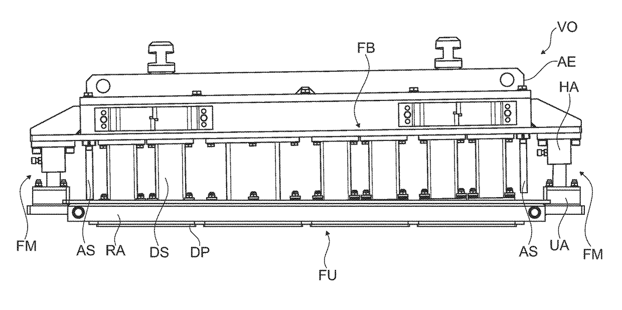
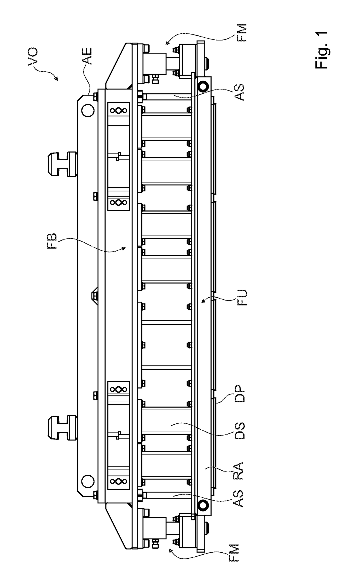
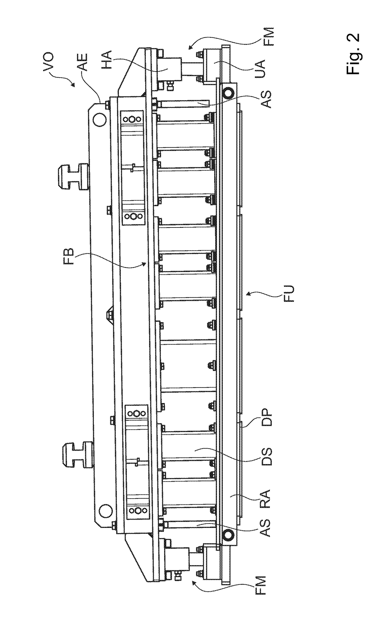
[0041]In FIG. 1, an apparatus VO is shown, which, is suitable for the production of molded concrete parts in a molding machine. The apparatus VO has a mold disposed in replaceable manner, which is formed by a lower mold part FU and an upper mold part FB. The lower mold part FU has a mold insert, in a manner usual in technology, which insert has a correspondingly selected number of openings, so that molded concrete parts can be produced in the desired number or size, using the apparatus VO.

[0042]The upper mold part FB has a plurality of pressure plates DP, wherein each pressure plate DP corresponds with an opening in the lower mold part FU. The pressure plates DP are connected with the punch plate ST by way of a pressure punch DS, in each instance.

[0043]Above the punch plate ST, a top-load device AS is provided, which can compress a concrete mixture introduced into t...


PUM

PropertyMeasurementUnit
angleaaaaaaaaaa
angleaaaaaaaaaa
heightaaaaaaaaaa

Abstract

An apparatus for the production of concrete molded parts in a molding machine includes an upper mold part having at least one pressure punch for transfer of a force to at least one pressure plate, wherein the pressure plate can be introduced into an opening of a mold insert in a lower mold part in the vertical direction, wherein the lower mold part is surrounded by a frame that has a guide connected with the upper mold part and configured so that, the lower mold part can be tilted from the vertical direction, relative to the upper mold part, during engagement of the pressure plates into the openings of the mold insert.

Description

CROSS REFERENCE TO RELATED APPLICATIONS[0001]Applicant claims priority under 35 U.S.C. §119 of German Application No. 10 2015 103 829.3 filed Mar. 16, 2015, the disclosure of which is incorporated by reference.BACKGROUND OF THE INVENTION[0002]1. Field of the Invention[0003]The invention relates to an apparatus for the production of molded concrete parts in a molding machine.[0004]2. Description of the Related Art[0005]Apparatuses for the production of molded concrete parts, such as paving bricks, for example, are typically used for machine production and contain a molding machine having a punch unit and a lower mold part configured as a mold, into which the punch unit can engage. Usually, one mold insert is or a number of mold, inserts are configured in the lower mold part, whose cavities are open toward the top and the bottom. The lower mold part is set onto a horizontal bed with a lower delimitation plane of a brick field, which bed closes off the lower openings of the mold. The m...

Claims


Application Information

Patent Timeline
Patent Type & Authority Patents(United States)
IPC IPC(8): B28B7/08B28B3/02B30B15/04B28B7/00B28B7/24
CPCB28B7/08B28B3/028B28B7/0097B28B7/24B30B15/041
Inventor STICHEL, HOLGERBRAUNGARDT, JUERGEN
Owner KOBRA FORMEN
Why Eureka
Try Eureka