Method and apparatus for detecting surroundings, and vehicle with such an apparatus

a technology of surroundings and apparatus, applied in the field of methods and apparatus for detecting surroundings, can solve the problems of short exposure time, significant lower resolution, and exposure between light pulses from the light signal

Active Publication Date: 2022-09-13
DAIMLER AG +1
View PDF19 Cites 0 Cited by
  • Summary
  • Abstract
  • Description
  • Claims
  • Application Information

AI Technical Summary

Problems solved by technology

However, they have significantly lower resolution.
Such short exposure times are problematic, however, if the camera images are also preferably supposed to be used to recognize light signals such as traffic lights, traffic signs configured as light signals, brake lights, turn signals, and similar light signals.
If the exposure times are too short, it gives rise to the danger that the ex

Method used


Image

  • Method and apparatus for detecting surroundings, and vehicle with such an apparatus

Examples


Embodiment Construction

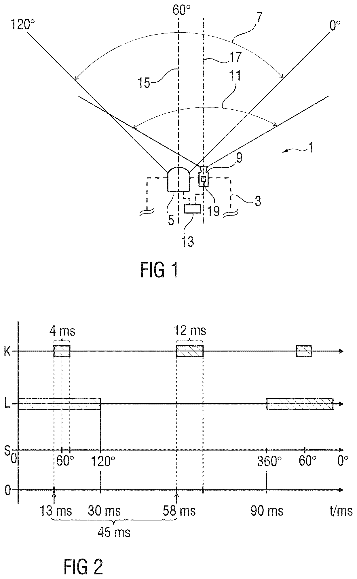
[0040]FIG. 1 shows a schematic representation of one example of an apparatus 1 for scanning surroundings, in particular the surroundings around a schematically represented vehicle 3, which can preferably be a motor vehicle, in particular a personal automobile, cargo vehicle, or utility vehicle.

[0041]The apparatus 1 comprises a laser scanner 5 configured to periodically scan the surroundings—here the surroundings around the vehicle 3—in a first detection region 7. The apparatus 1 further comprises an optical camera 9 configured to detect the surroundings in a second detection region 11. Here the first detection region 7 and the second detection region 11 at least partially overlap each other. The apparatus 1 further has a control unit 13 operatively connected to both the laser scanner 5 and the optical camera 9 so that the control unit 13 can control the laser scanner 5 and the optical camera 9.

[0042]Here the control unit 13 is configured to execute the above-described method as expl...


PUM


Abstract

A method and apparatus for detecting surroundings around a vehicle may include the step of periodically scanning the surroundings in a first detection region by a laser scanner. The method may also include detecting the surroundings in a second detection region by an optical camera. The first detection region and the second detection region may at least overlap each other. An optical sensor in the camera may be exposed at least twice within one period of the laser scanner. A first exposure time for a first exposure of the at least two exposures of the optical sensor may be chosen and synchronized with the laser scanner so that the first exposure occurs within a first time window, in which the laser scanner scans the first detection region.

Description

BACKGROUND OF THE INVENTION[0001]The invention concerns a method and an apparatus for detecting surroundings, in particular the surroundings around a vehicle, and a vehicle with such an apparatus.[0002]It is known to combine optical cameras with laser scanning processes or laser scanners for detection of surroundings, in particular in vehicles. For example, the US American patent application US 2016 / 0180177 A1 discloses a system installed in a motor vehicle for detecting the border of a road lane, which has both a camera and a LiDAR detector, wherein a first probabilistic model for the lane border is generated from the camera data, wherein a second probabilistic model for the lane border is generated from the LiDAR data, and wherein the probabilistic models thus generated are merged with each other to get a fused probabilistic model from which the lane border is detected.[0003]The German published patent application DE 10 2017 108 248 A1 discloses a computer-implemented road feature...

Claims


Application Information

Patent Timeline
IPC IPC(8): G06K9/00G01S17/86G01S17/89G01S17/931G06K9/20G06K9/62G08G1/04H04N5/235G06V20/58G06V10/22
CPCG06V20/584G01S17/86G01S17/89G01S17/931G06K9/6289G06V10/22G08G1/04H04N5/2353G06F18/251H04N23/73
Inventor SCHAEFER, MANUELGRESSMANN, MARKUSEGGERS, HELMUTHLEHNER, PHILIPPMEINKE, MARTIN
Owner DAIMLER AG
Why Eureka
Try Eureka