
Cosmetic equipment shield

a technology of equipment shields and shields, applied in the direction of lighting and heating apparatus, space heating and ventilation, heating types, etc., can solve the problems of reducing the efficiency of equipment, affecting the visual appearance of the building, and the existing wall cannot be positioned properly

Active Publication Date: 2022-09-27
WOJCIK ROSS
View PDF17 Cites 0 Cited by
  • Summary
  • Abstract
  • Description
  • Claims
  • Application Information

AI Technical Summary

Benefits of technology

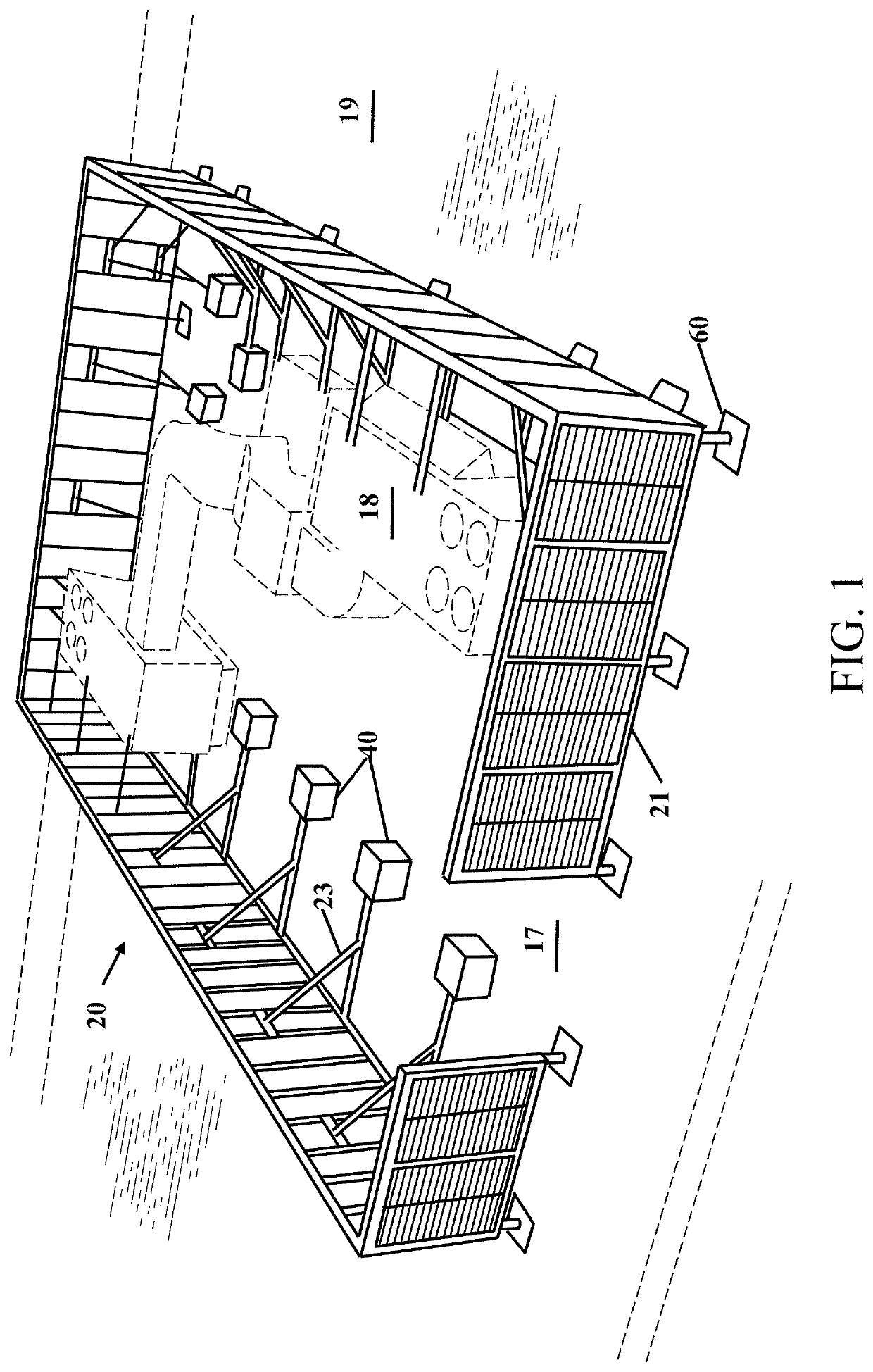
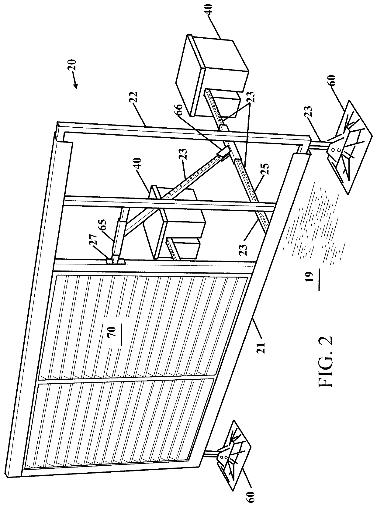
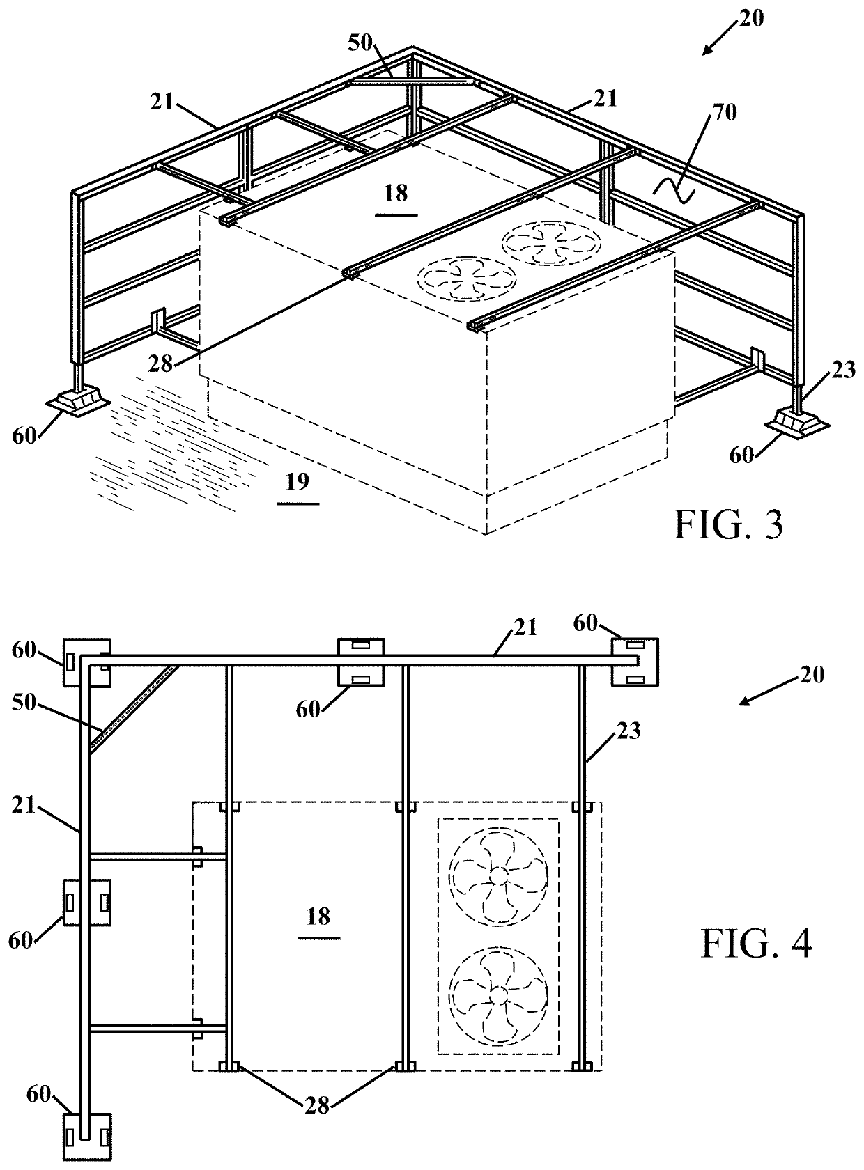
The patent describes a cosmetic equipment shield that can be installed on a building roof to improve its appearance. The shield can cover all the equipment on the roof and is easily erected to provide a continuous shield that convers the roof equipment on one, two, three or all 4 sides. It is supported on the roof with mount brackets and arms that secure into the existing roof. The shield is designed to resist weather conditions such as rain, wind, hot temperatures and freezing temperatures. It can be configured and configurable for a nearly infinite straight side and can also include angle brackets to change the direction of the shield. Overall, the shield improves the visual appearance of the building and enhances the structural rigidity of the equipment shield.

Problems solved by technology

This equipment often sits above the building where it can be ugly and can detract from the visual appearance of the building.
Sometimes a wall is built around the equipment to reduce the appearance from the ground, but when the equipment is replaced the existing wall does not fit.
A standard wall can also restrict air movement and reduce the efficiency of the equipment.
Another problem is with walls that do not match the color of a building or a miss-match of wall construction and heights.
This cover mounts to the curb of the equipment for support and is not free standing.
These patents do not provide a structural connection to a roof to prevent damage in high wind areas.

Method used


Image

  • Cosmetic equipment shield
  • Cosmetic equipment shield
  • Cosmetic equipment shield

Examples


Embodiment Construction

[0026]It will be readily understood that the components of the present invention, as generally described and illustrated in the drawings herein, could be arranged and designed in a wide variety of different configurations. Thus, the following more detailed description of the embodiments of the system and method of the present invention, as represented in the drawings, is not intended to limit the scope of the invention, but is merely representative of various embodiments of the invention. The illustrated embodiments of the invention will be best understood by reference to the drawings, wherein like parts are designated by like numerals throughout.

ITEM NUMBERS AND DESCRIPTION

[0027]

17opening18equipment19roof20equipment screen21track(s)22panel frame23telescoping support25holes27enclosed bracket28corner clip40ballasted stabilizer50inside bracket51arm52angle bracket53hole(s)54angle bracket55“U” tube56“U” tube57“L” bracket58“U” tube60rooftop support base65angle bracket66angle bracket70pan...


PUM


Abstract

Improvements in a cosmetic equipment shield that provides a cosmetic shield that can cover all of the equipment that can exist on the roof of a building is disclosed. The cosmetic shield convers the roof equipment on one or more sides to improve the visual appearance of the building. The shield allows air movement through the cosmetic shield. The metal strips are staggered, offset or otherwise configured so they prevent viewing through the metal strips or louvers, but allows air flow. The cosmetic equipment shield is secured to the roof to resist most weather conditions from rain to wind, hot temperatures and freezing temperatures. The cosmetic equipment shield is configured for nearly infinite straight walls and can also include angle brackets to change the direction of the shield to 90 degrees or 270 degrees or can be angled slightly in a curved appearance.

Description

CROSS REFERENCE TO RELATED APPLICATIONS[0001]This application claims the benefit of Provisional Application Ser. No. 62 / 851,195 filed May 22, 2019 the entire contents of which is hereby expressly incorporated by reference herein.STATEMENT REGARDING FEDERALLY SPONSORED RESEARCH OR DEVELOPMENT[0002]Not ApplicableTHE NAMES OF THE PARTIES TO A JOINT RESEARCH AGREEMENT[0003]Not ApplicableINCORPORATION-BY-REFERENCE OF MATERIAL SUBMITTED ON A COMPACT DISC[0004]Not ApplicableBACKGROUND OF THE INVENTIONField of the Invention[0005]This invention relates to improvements in a configurable structural shield that surrounds equipment. More particularly, the present cosmetic equipment shield allows for erecting an ornamental structure around roof or ground mounted equipment to improve the cosmetic appearance of a building.Description of Related Art including information disclosed under 37 CFR 1.97 and 1.98[0006]When buildings are constructed the roof of the building typically includes heating venti...

Claims


Application Information

Patent Timeline
IPC IPC(8): F24F13/20E04B2/76F24F13/15E04D13/00E04B2/74
CPCF24F13/20E04B2/7409E04B2/7435E04B2/76E04D13/00F24F13/15F24F2221/16F24F2221/26
Inventor WOJCIK, ROSS
Owner WOJCIK ROSS
Learn More