Valve unit

a valve unit and valve body technology, applied in the direction of valve operating means/releasing devices, mechanical equipment, clutches, etc., can solve the problems of increased cost and inappropriate pressure adjustmen

Active Publication Date: 2022-10-04
KUBOTA CORP
View PDF14 Cites 0 Cited by
  • Summary
  • Abstract
  • Description
  • Claims
  • Application Information

AI Technical Summary

Benefits of technology

[0018]The above characteristic arrangement involves keeping the pressure adjustment valve body at a closed position when the pressure of the supply oil passage is smaller than a set value and allowing the pressure adjustment valve body to open when the pressure of the supply oil passage is not smaller than the set value. This allows the supply oil passage to keep its pressure at not smaller than the set value. The above characteristic arrangement also includes a restriction member configured to restrict the amount of movement of the pressure adjustment valve body if the pressure of the supply oil passage has been increased sharply. This prevents the spring from becoming compressed greatly, and thereby prevents a decrease in its urging force.
[0019]The above characteristic arrangement thereby allows a valve unit capable of continuing appropriate pressure adjustment to be produced without a cost increase.
[0026]The above arrangement places a bar-shaped restriction member inside the coil of the spring. The restriction member can thus prevent excessive compression of the spring without the need to have a complicated structure.
[0031]The above arrangement allows operating oil from the hydraulic pump to be supplied sequentially to the power steering unit, the valve unit, and the continuously variable transmission device in this order. The arrangement in this order allows (i) operating oil with a high pressure to be supplied to the power steering unit, (ii) operating oil with a pressure lower than the above pressure to be supplied via the valve unit to, for example, a hydraulic clutch, and (iii) operating oil with a pressure even lower than the above pressure to be supplied to the continuously variable transmission device as charge oil. The above arrangement thus makes it possible to avoid wasting operating oil and eliminates the need to include a plurality of hydraulic pumps.
[0039]Typically, such a friction clutch can be kept engaged even with the operating oil having a lower pressure, compared with the pressure of operating oil to be supplied to a hydraulic cylinder that drives e.g. a bucket and an arm of an excavator adapted to be connected to a tractor. Thus, with the above arrangement, operating oil supplied through the control port has a relatively low pressure. This allows the pressure on the spring to be relatively small, and effectively prevents plastic deformation of the spring.

Problems solved by technology

The relief valve, however, has a complicated structure and leads to a cost increase.
However, repeated compression of the spring decreases its urging force to be applied to the valve body, disadvantageously leading to inappropriate pressure adjustment.

Method used


Image

  • Valve unit
  • Valve unit
  • Valve unit

Examples


Embodiment Construction

[0054]An embodiment of the invention will be described hereinafter with reference to the drawings.

[Overall Configuration]

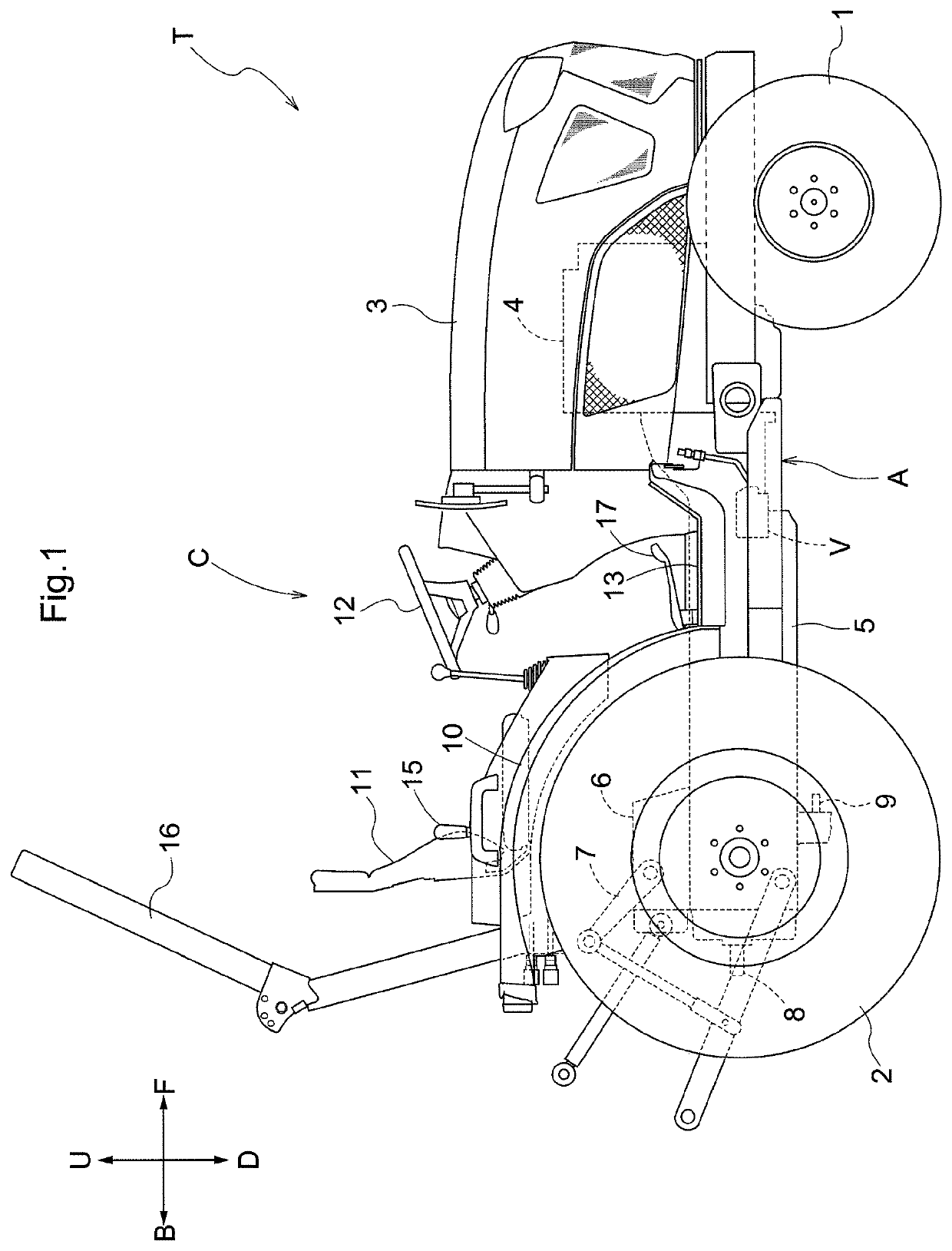
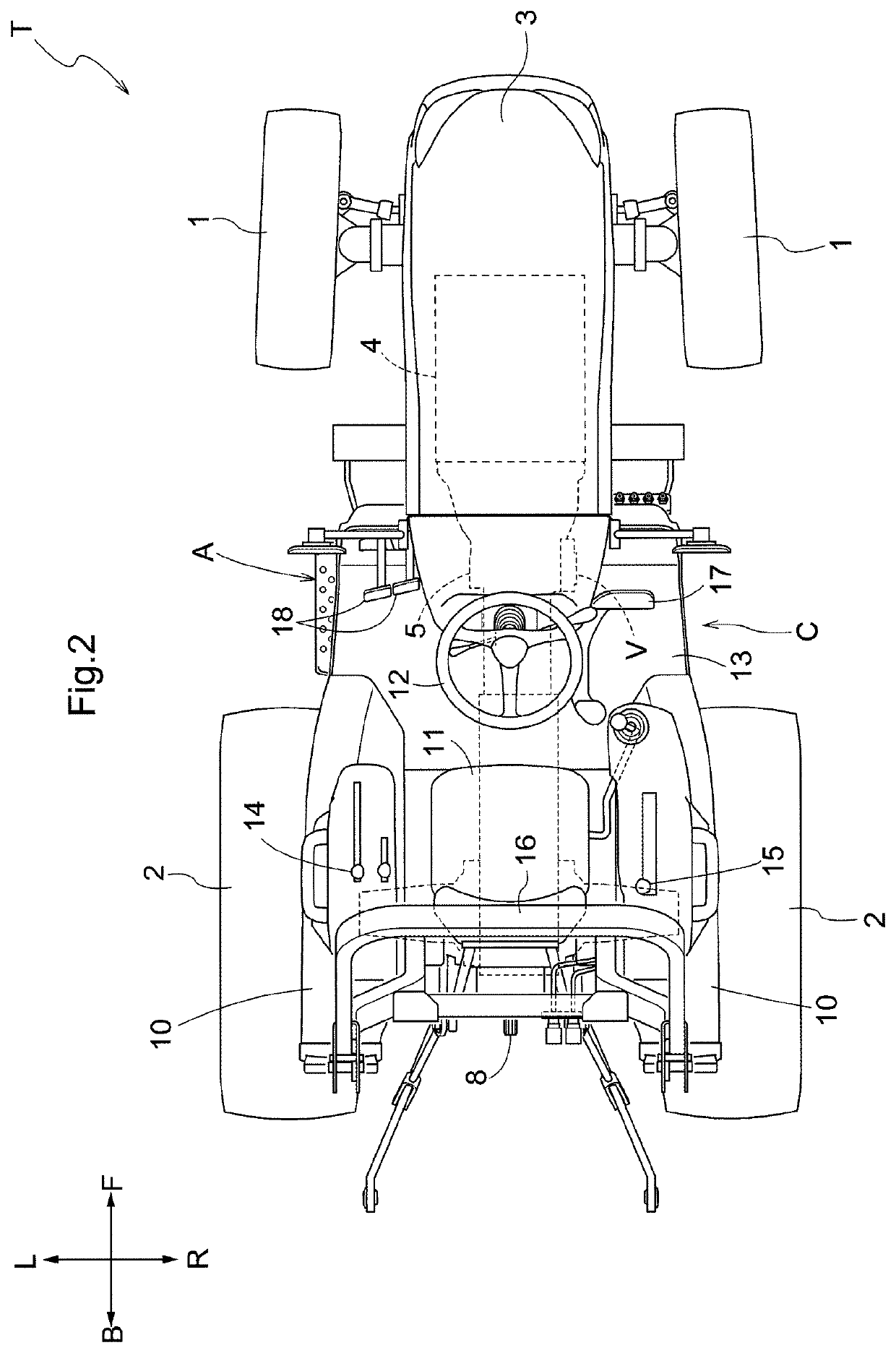
[0055]As shown in FIGS. 1 and 2, a tractor T is illustrated as an exemplary work machine (work vehicle), including a machine body A provided with a pair of right and left front wheels 1 and a pair of right and left rear wheels 2; an engine 4 covered by an engine hood 3 at a forward portion of the machine body A; and a driver section C at a rear portion of the machine body A.

[0056]In following description, “F” shown in FIGS. 1 and 2 depicts to indicate the forward direction, “B” the backward direction, “U” the upward direction, “D” the downward direction, “R” the rightward direction, and “L” the leftward direction.

[0057]The tractor T further includes: a transmission case 5 in an area extending from a central portion of the machine body A to the back end thereof for varying the driving force of the engine 4; a lift cylinder 6 housed in the transmission case 5 at a r...


PUM


Abstract

A valve unit (V) has a valve housing (50) that includes a supply oil passage (55) configured to receive operating oil from a hydraulic pump, and a pressure adjustment valve (Va) configured to adjust the pressure of the supply oil passage (55). The pressure adjustment valve (Va) includes a pressure adjustment valve body (61) configured to open and close the supply oil passage (55), a compression coil spring (62) that keeps the pressure adjustment valve body (61) at a closed position when the pressure of the supply oil passage (55) is smaller than a set value and allows the pressure adjustment valve body (61) to open when the pressure of the supply oil passage (55) is not smaller than the set value, and a restriction member (63) configured to, when the pressure adjustment valve body (61) becomes open against the urging force of the spring (62) in response to a pressure of the operating oil, abut against the pressure adjustment valve body (61) to restrict movement of the pressure adjustment valve body (61).

Description

CROSS-REFERENCE TO RELATED APPLICATION[0001]This application claims priority to Japanese Patent Application No. 2019-237396 filed Dec. 26, 2019, the disclosure of which is hereby incorporated by reference in its entirety.BACKGROUND OF THE INVENTION1. Field of the Invention[0002]The present invention relates to a valve unit including a pressure adjustment valve configured to adjust the pressure of operating oil.2. Description of Related Art[0003]JP H08-028601 A discloses a relief valve of a hydraulic, gradual increase type configured to adjust the pressure of operating oil to be supplied to a hydraulic clutch.[0004]In a valve unit thereof, a cylindrical valve case is housed in a valve housing; and a relief valve body and a control piston are housed in the valve case, with a spring being arranged between the relief valve body and the control piston.[0005]JP H08-028601 A discloses an oil chamber that has a pump port communicating with an operating oil supply passage, and an oil drain p...

Claims


Application Information

Patent Timeline
Patent Type & Authority Patents(United States)
IPC IPC(8): F16D48/02F15B7/06
CPCF16D48/02F15B7/06F15B2211/522F15B13/024F15B13/0405F15B13/044F15B2211/327F15B2211/365F15B2211/50518F15B2211/528F15B2211/55F15B2211/7052F16K31/0665
Inventor OKAMOTO, NAOYATOTTORI, NORITA
Owner KUBOTA CORP
Why Eureka
Try Eureka