Switch apparatus for automobile

a technology for switching apparatuses and automobiles, applied in dashboard fitting arrangements, instruments, pulse techniques, etc., can solve the problems of unsecure space for installing touch-type switch apparatuses, and achieve the effects of preventing external moisture from directly flowing, and reducing the size of the main body

Active Publication Date: 2022-10-04
SEOYON ELECTRONICS CO LTD
View PDF14 Cites 0 Cited by
  • Summary
  • Abstract
  • Description
  • Claims
  • Application Information

AI Technical Summary

Benefits of technology

[0052]In the switch apparatus for an automobile according to the present disclosure, the wheel knob of the dial switch apparatus is formed in an annular shape, and the capacitive touch pad of the touch type switch apparatus is disposed in the inner space of the wheel knob. Accordingly, the touch type switch apparatus is installed inside the dial switch apparatus, and thus, a size thereof can be reduced.
[0053]Moreover, the first drain rib is formed in the main body, the through hole is formed in the main PCB, and the second drain rib is formed in the cover body. The first drain rib passes through the through hole and is inserted into the second drain rib. The first drain hole extending downward from the bottom surface of the input unit insertion groove is formed inside the first drain rib, and the second drain hole into which the first drain rib is inserted is formed inside the second drain rib. Accordingly, when moisture is introduced into the input unit insertion groove through the dial switch apparatus and the touch type switch apparatus, the introduced moisture is discharged to the lower side of the cover body through the first drain hole and the second drain hole. Therefore, there is no need to provide a drainage structure outside the periphery of the main PCB in the main body, and thus, a size of the main body can be reduced.
[0054]The ring insertion groove into which the lower end of the mood ring is inserted is formed in the main body, and the transparent portion through which light generated by the light source passes and which is formed of a transparent material is formed on the bottom surface of the ring insertion groove. Accordingly, the mood ring can be illuminated by the light, and it is possible to prevent external moisture from directly flowing into the main PCT through the mood ring.
[0055]Moreover, the case of the touch type switch apparatus is illuminated, and thus, a user can recognize a position of the capacitive touch pad through subtle light emitted from the case and emotions of the user can be improved.

Problems solved by technology

Accordingly, there is no inner space, and thus, a space for installing the touch type switch apparatus is not secured.

Method used


Image

  • Switch apparatus for automobile
  • Switch apparatus for automobile
  • Switch apparatus for automobile

Examples


Embodiment Construction

[0087]Advantages and features of the present disclosure, and a method of achieving the advantages and features will become apparent with reference to embodiments described below in detail with the accompanying drawings. However, the present disclosure is not limited to the embodiments disclosed below, but may be implemented in a variety of different forms. The embodiments are provided to ensure that the disclosure of the present disclosure is complete, and to fully inform the scope of the invention to those with ordinary skill in the technical field to which the present disclosure belongs, and the present disclosure is only defined by the scope of the claims. The same reference numerals refer to the same components throughout the specification.

[0088]Hereinafter, a switch apparatus for an automobile according to an embodiment of the present disclosure will be described with reference to the drawings.

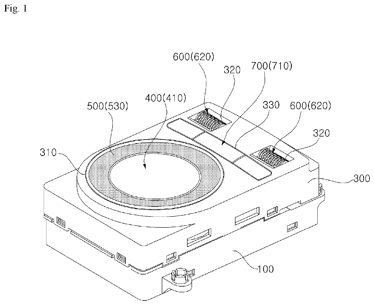
[0089]FIG. 1 is a combined perspective view illustrating a switch apparatus for an au...


PUM


Abstract

A switch apparatus for an automobile with a reduced size by installing a touch type switch apparatus inside a dial switch apparatus is provided. A switch apparatus for an automobile according to the present disclosure includes a main body which has an open lower side, a cover body which is inserted into the open lower side of the main body and is coupled to the main body, a dial switch apparatus which is installed on the main body and has an annular wheel knob rotatable with a virtual rotation axis disposed in a vertical direction as a rotation center, a touch type switch apparatus which is installed on the main body and has a capacitive touch pad which is touched by a user and pressed in an up-down direction, a main PCB which is coupled to the cover body to be disposed in the main body and into which a switch signal is input from the dial switch apparatus and the touch type switch apparatus, and a case body which is coupled to the main body and has a hole, through which the wheel knob and the capacitive touch pad are exposed, on an upper side, in which the capacitive touch pad is disposed inside the wheel knob.

Description

BACKGROUND OF THE DISCLOSUREField of the Disclosure[0001]The present disclosure relates to a switch apparatus for an automobile, and more particularly, to a switch apparatus for an automobile in which a plurality of switch apparatuses are installed in one body.Related Art[0002]In general, various switch apparatuses are installed in an interior of an automobile, and the switches are classified in various ways according to an operation method of a knob provided in a switch signal input unit. That is, the switches are classified into a push switch apparatus in which a knob is linearly moved by pushing of a user to generate different switch signals according to a linear movement amount of the knob, a seesaw switch apparatus in which the knob is rotated in one direction about a horizontally disposed rotating shaft to generate a first switch signal and the knob is rotated in the other direction to generate a second switch signal, and a rotary switch apparatus in which the knob is rotated ...

Claims


Application Information

Patent Timeline
Patent Type & Authority Patents(United States)
IPC IPC(8): H01H19/14H01H13/06H01H13/14H01H19/02H01H25/06H03K17/96
CPCH01H19/14H01H13/06H01H13/14H01H19/025H01H25/06H03K17/962H01H2219/036H01H2231/026G06F3/0362G06F3/03547G06F3/016B60K37/06B60K2370/1434B60K2370/137B60K2370/126B60K2370/341B60K2370/91B60K35/00H01H19/11H03K2217/94068H03K2217/96042
Inventor KIM, KIWONKIM, GYUHOPARK, SANGKILHER, SEULGICHANSONG, MYUNGJIN
Owner SEOYON ELECTRONICS CO LTD
Why Eureka
Try Eureka