
Vacuum system with a multi-stage and multi-inlet vacuum pump with a directional element separating pump stages

a vacuum pump and vacuum chamber technology, applied in the field of vacuum systems, can solve the problems of significant high pumping speed and notably low pressure in the vacuum chamber

Active Publication Date: 2022-10-25
PFEIFFER VACUUM GMBH +1
View PDF9 Cites 0 Cited by
  • Summary
  • Abstract
  • Description
  • Claims
  • Application Information

AI Technical Summary

Benefits of technology

The invention aims to enhance the pumping speed of a vacuum chamber without significantly increasing expense or size.

Problems solved by technology

This leads to a significantly high pumping speed and, thus, to a notably low pressure in the vacuum chamber.

Method used


Image

  • Vacuum system with a multi-stage and multi-inlet vacuum pump with a directional element separating pump stages
  • Vacuum system with a multi-stage and multi-inlet vacuum pump with a directional element separating pump stages
  • Vacuum system with a multi-stage and multi-inlet vacuum pump with a directional element separating pump stages

Examples


Embodiment Construction

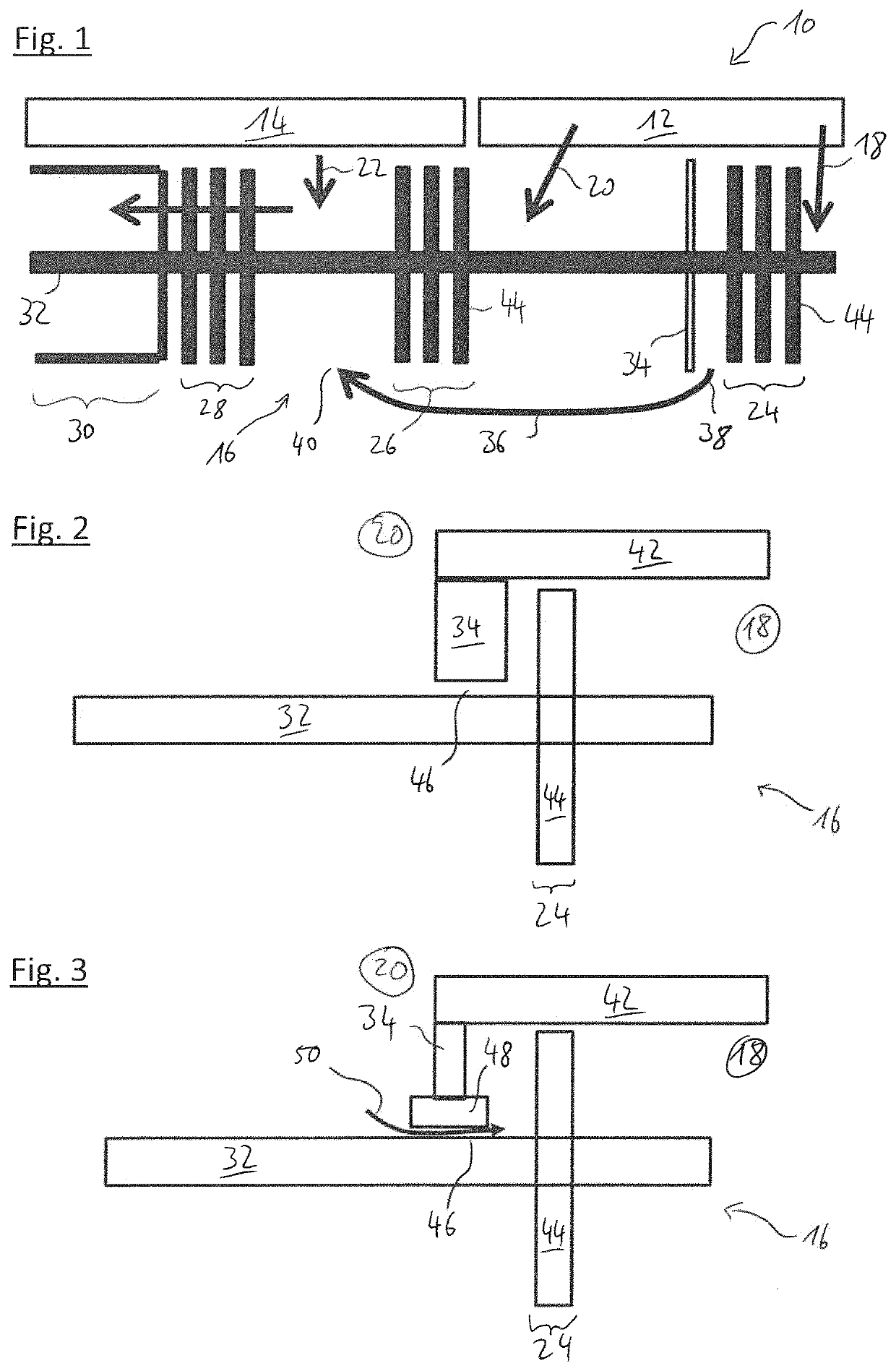
[0047]In FIG. 1, a vacuum system 10 in accordance with the invention is shown. The vacuum system 10 comprises two vacuum chambers, a first vacuum chamber 12 and a second vacuum chamber 14. The vacuum chambers 12, 14 are connected to respective inlets of a vacuum pump 16.

[0048]In particular, the pump comprises a first inlet 18 and a second inlet 20, both connected to the same vacuum chamber, i.e. the first vacuum chamber 12. The vacuum pump 16 further comprises a third inlet 22 connected to the second vacuum chamber 14. The inlets 18, 20, 22 are indicated as respective arrows representing a gas stream during pumping action.

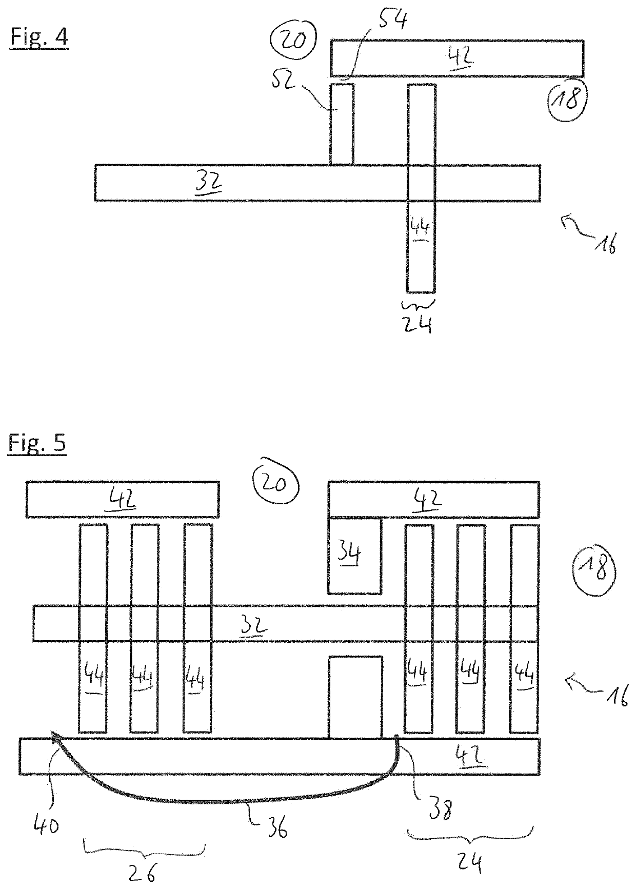
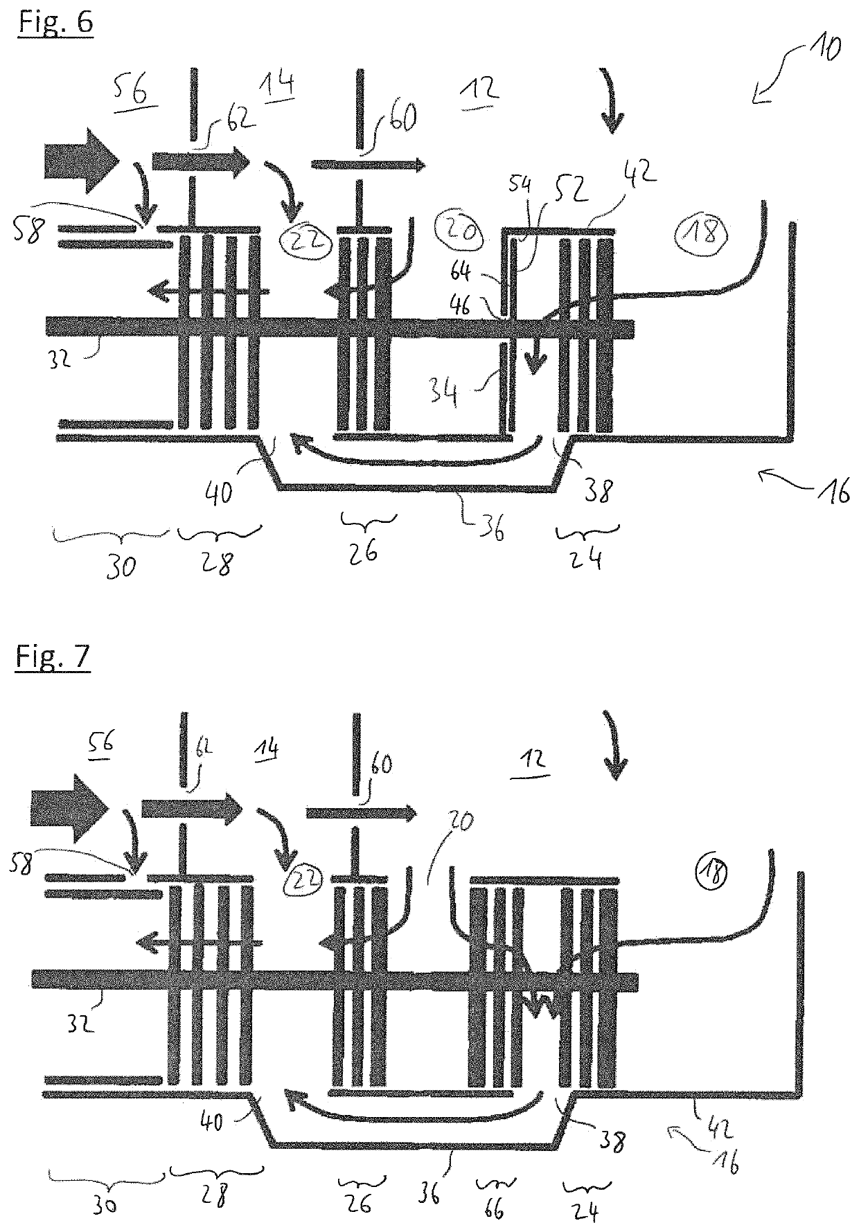
[0049]The vacuum pump 16 is, in this example, a turbomolecular and split-flow pump and comprises a first pumping stage 24, a second pumping stage 26, a third pumping stage 28 and a fourth pumping stage 30, wherein each pumping stage comprises at least one rotor element 44, three in this embodiment, arranged on a common rotor shaft 32. The rotor shaft 32 forms a rot...


PUM


Abstract

The invention relates to a vacuum system, comprising a vacuum pump, preferably turbomolecular pump, and at least one vacuum chamber, wherein the vacuum pump comprises: at least a first and a second inlet and a common outlet; at least a first and a second pumping stage, each pumping stage comprising at least one rotor element being arranged on a common rotor shaft, wherein the first inlet is connected to an upstream end of the first pumping stage and the second inlet is connected to an upstream end of the second pumping stage; a direction element for preventing a gas flow from a downstream end of the first pumping stage to the second inlet; a conduit having a conduit inlet and a conduit outlet, wherein the conduit inlet is connected to the downstream end of the first pumping stage and the conduit outlet is connected to a location downstream of the second pumping stage; wherein the first inlet and the second inlet of the pump are connected to the same vacuum chamber.

Description

CROSS-REFERENCE TO RELATED APPLICATION[0001]This application claims priority to European application no. EP 19186289.5, filed Jul. 15, 2019, the content of which is incorporated by reference herein in its entirety.FIELD OF INVENTION[0002]The present invention is directed to a vacuum system, comprising a vacuum pump, preferably a turbomolecular pump, and at least one vacuum chamber, wherein the vacuum pump comprises: at least a first and a second inlet and a common outlet; at least a first and a second pumping stage, each pumping stage comprising at least one rotor element being arranged on a common rotor shaft, wherein the first inlet is connected to an upstream end of the first pumping stage and the second inlet is connected to an upstream end of the second pumping stage; a direction element for preventing a gas flow from a downstream end of the first pumping stage to the second inlet; a conduit having a conduit inlet and a conduit outlet, wherein the conduit inlet is connected to ...

Claims


Application Information

Patent Timeline
Patent Type & Authority Patents(United States)
IPC IPC(8): F04D19/04F04D19/02
CPCF04D19/042F04D19/022F04D19/028F04D19/044F04D25/16H01J49/24F04D29/102
Inventor STOLL, TOBIASSCHWEIGHOEFER, MICHAELHOFFMANN, JANBERTSCH, JAMES L.
Owner PFEIFFER VACUUM GMBH
Learn More