Adsorption and condensation type oil gas recovery device and adsorption and condensation type oil gas recovery process by self-adsorptive heat regeneration

A recovery device and thermal regeneration technology, which can be used in the petroleum industry, recovery of liquid hydrocarbon mixtures, gas treatment, etc., and can solve the problem of increased investment in dry vacuum pumps

Active Publication Date: 2017-06-09
上海聚宸新能源科技有限公司
View PDF7 Cites 9 Cited by
  • Summary
  • Abstract
  • Description
  • Claims
  • Application Information

AI Technical Summary

Problems solved by technology

If frequency conversion is used to control the actual flow rate of the vacuum pump, in order to meet the process requirements of desorption within 10 to 20 minutes, the dry vacuum pump needs to be increased by several orders of magnitude to achieve this rate requirement, resulting in a sharp increase in the investment of the dry vacuum pump

Method used


Image

  • Adsorption and condensation type oil gas recovery device and adsorption and condensation type oil gas recovery process by self-adsorptive heat regeneration
  • Adsorption and condensation type oil gas recovery device and adsorption and condensation type oil gas recovery process by self-adsorptive heat regeneration
  • Adsorption and condensation type oil gas recovery device and adsorption and condensation type oil gas recovery process by self-adsorptive heat regeneration

Examples


Embodiment 1

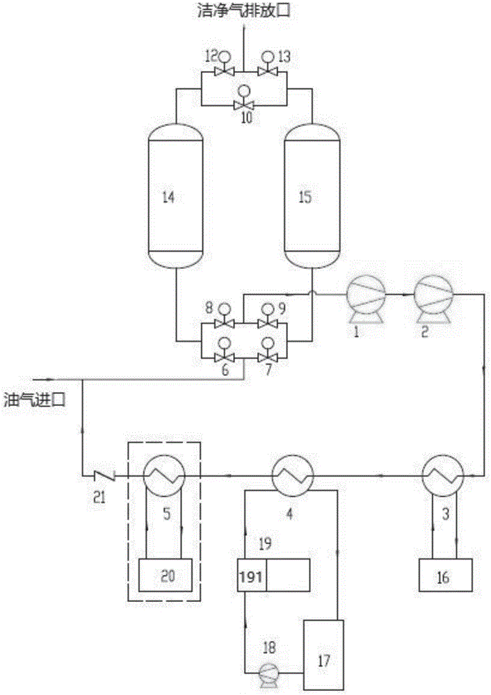
[0100] join figure 1 , the invention discloses an adsorption condensed oil gas recovery device utilizing self-adsorption heat regeneration, including an oil gas inlet, a first valve group, a Roots vacuum pump 1, a dry vacuum pump 2, a first-stage oil-gas condenser 3, and a second-stage oil-gas condenser 4. Three-stage oil-gas condenser 5. Check valve 21, adsorption tank group, second valve group, clean gas discharge port, of which:

[0101] The first valve group is composed of an intake valve group and a vacuum valve group connected in parallel below the adsorption tank group;

[0102] The second valve group is composed of an exhaust valve group located above the adsorption tank group and a balance purge valve 10 connected in parallel;

[0103] The balance purge valve 10, adsorption tank group, vacuum valve group, Roots vacuum pump 1, dry vacuum pump 2, first-stage oil-gas condenser 3, second-stage oil-gas condenser 4, third-stage oil-gas condenser 5 and check valve 21 are c...

Embodiment 2

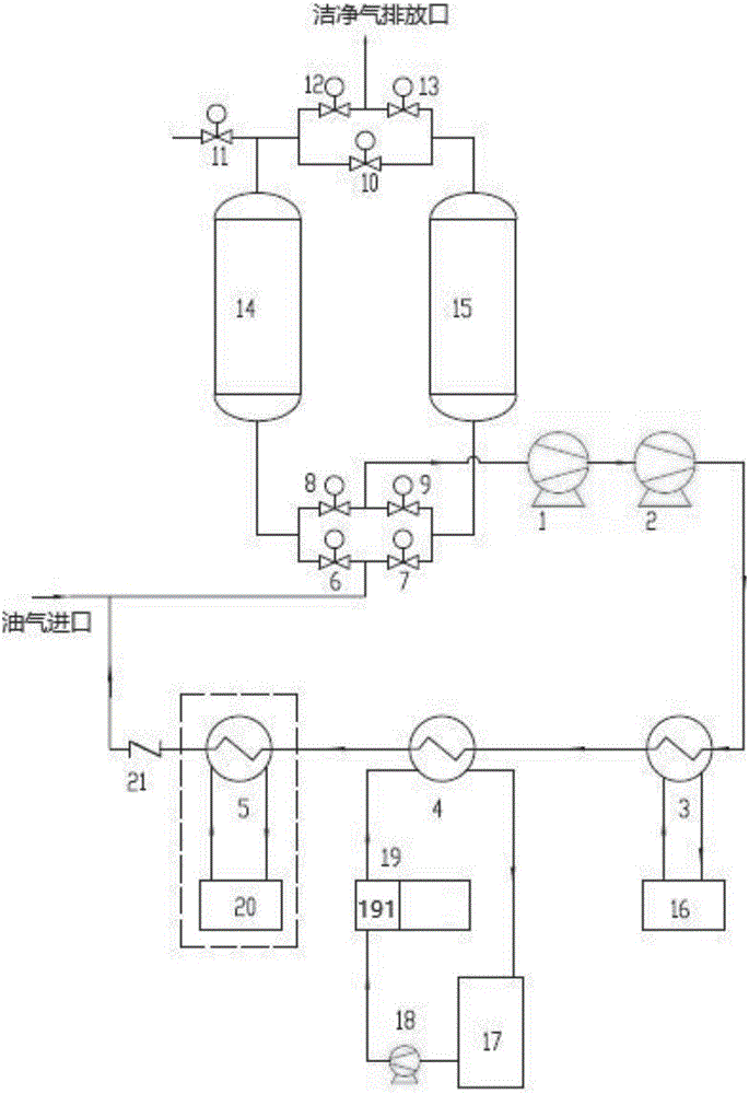
[0124] see Figure 5 , the present invention also discloses an adsorption condensation oil gas recovery process utilizing self-adsorption heat regeneration, comprising the following steps:

[0125] Step 1: The oil and gas to be treated enter through the oil and gas inlet, mix with a very small amount of uncondensed oil and gas discharged from the oil and gas condensing system (first-stage oil-gas condenser 3, second-stage oil-gas condenser 4 and third-stage oil-gas condenser 5), and then pass through the inlet The gas valve group enters the corresponding activated carbon adsorption tank, and the oil and gas enter the left adsorption tank 14 through the left oil and gas inlet valve 6, and are adsorbed and intercepted by the adsorbent in the left adsorption tank 14, and the remaining clean exhaust gas is heated by the adsorption heat and then discharged through the left oil and gas outlet valve 12 Into the atmosphere, while the left adsorption tank 14 is adsorbing oil and gas, t...

Embodiment 3

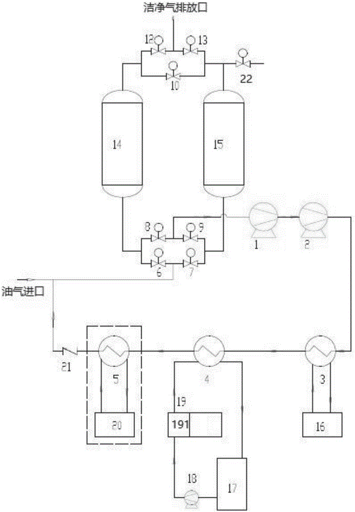
[0129] see Image 6, the present invention also discloses an adsorption condensation oil gas recovery process utilizing self-adsorption heat regeneration, comprising the following steps:

[0130] Step A: The oil and gas to be treated enter through the oil and gas inlet, mix with a very small amount of uncondensed oil and gas discharged from the oil and gas condensing system (first-stage oil-gas condenser 3, second-stage oil-gas condenser 4 and third-stage oil-gas condenser 5), and then pass through the inlet The gas valve group enters the corresponding activated carbon adsorption tank, and the oil and gas enter the right adsorption tank 15 through the right oil and gas inlet valve 7, and are adsorbed and intercepted by the adsorbent in the right adsorption tank 15, and the remaining clean exhaust gas is heated by the adsorption heat and then discharged through the right oil and gas outlet valve 13 Into the atmosphere, while the right adsorption tank 15 is absorbing oil and gas...


PUM


Abstract

The invention discloses an adsorption and condensation type oil gas recovery device and an adsorption and condensation type oil gas recovery process by self-adsorptive heat regeneration. The adsorption and condensation type oil gas recovery device by the self-adsorptive heat regeneration comprises an oil gas inlet, a first valve group, a Roots vacuum pump, a dry vacuum pump, a primary oil gas condenser, a secondary oil gas condenser, a tertiary oil gas condenser, a check valve, an adsorption tank group, a second valve group and a clean gas discharge outlet. The first valve group comprises a gas inlet valve group and a vacuum valve group, wherein the gas inlet valve group and the vacuum valve group which are in parallel connection are arranged below the adsorption tank group. The second valve group comprises a gas discharge valve group and a balanced purge valve, wherein the gas discharge valve group and the balanced purge valve are in parallel connection and arranged over the adsorption tank group. The balanced purge valve, the adsorption tank group, the vacuum valve group, the Roots vacuum pump, the dry vacuum pump, the primary oil gas condenser, the secondary oil gas condenser, the tertiary oil gas condenser and the check valve are connected in sequence, and then the check valve is connected with the oil gas inlet. The oil gas inlet is sequentially connected with the gas inlet valve group, the adsorption tank group, the gas discharge valve group and the clean gas discharge outlet.

Description

technical field [0001] The invention relates to the technical field of oil and gas recovery, in particular to an adsorption condensation oil and gas recovery device and an oil and gas recovery process utilizing self-adsorption heat regeneration. Background technique [0002] Oil and gas is a kind of VOC (Volatile Organic Compounds, volatile organic compounds) gas, which is generally a mixture containing volatile organic gases and a large amount of non-condensable gases. [0003] The existing mainstream oil and gas recovery and treatment processes generally include condensation + adsorption process, compression condensation + membrane + adsorption process, adsorption + absorption process, etc. [0004] 1. Condensation + adsorption process, it is necessary to make the volatile organic gas and non-condensable gas in the oil and gas phase change when they are not separated. At this time, the partial pressure of the volatile organic gas is very low. Correspondingly, the phase cha...

Claims


Application Information

Patent Timeline
Patent Type & Authority Applications(China)
IPC IPC(8): B01D53/04B01D53/00B01D5/00C10G5/02C10G5/06
CPCB01D5/0036B01D5/0054B01D53/002B01D53/04C10G5/02C10G5/06B01D2259/4009
Inventor 白爽
Owner 上海聚宸新能源科技有限公司
Why Eureka
Try Eureka