Vacuum pump for differential pumping multiple chambers

a vacuum pump and multiple chamber technology, applied in the field of vacuum pumps, can solve the problems of pressure drop, affecting the performance of the pump, and affecting the pumping speed, and achieve the effect of simple construction

Active Publication Date: 2010-10-12
EDWARDS LTD
View PDF12 Cites 9 Cited by
  • Summary
  • Abstract
  • Description
  • Claims
  • Application Information

AI Technical Summary

Benefits of technology

[0010]With such an orientation of the pump relative to the pressure chambers, the conductance of the inlets of the pump can be maximised and high effective pumping speeds can be achieved for a given pumping mechanism. Furthermore, since the pump protrudes into the chambers, the overall volume occupied by the chambers and pump is minimised.
[0012]The pump is preferably in the form of a cartridge inserted into a housing attached to or part of the mass spectrometer such that the cartridge protrudes through a mouth of the housing into said at least one of the chambers. This can provide a relatively simple construction for mounting and aligning the pump relative to the chambers under evacuation, as opposed to an arrangement wherein the pump is integrated into the body of the mass spectrometer.

Problems solved by technology

However, when mounted to a mass spectrometer in a conventional manner, for example with the axis of the pump, or more particularly, its shaft axis, either parallel to or perpendicular to the plane of the outlet flanges of the mass spectrometer, conductance limitations of such a split flow pump compromise performance in comparison to an arrangement where adjacent chambers are evacuated using a bespoke vacuum pump directly mounted on to the respective chamber.
For example, when the pump is orientated with respect to the mass spectrometer such that the shaft axis is parallel to the plane of the outlet flanges, then gas must flow around a right angle bend to enter the pump inlet, which results in a pressure drop and associated loss of pumping speed.

Method used


Image

  • Vacuum pump for differential pumping multiple chambers
  • Vacuum pump for differential pumping multiple chambers
  • Vacuum pump for differential pumping multiple chambers

Examples


Embodiment Construction

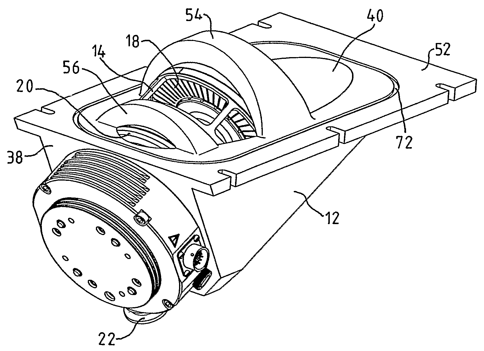
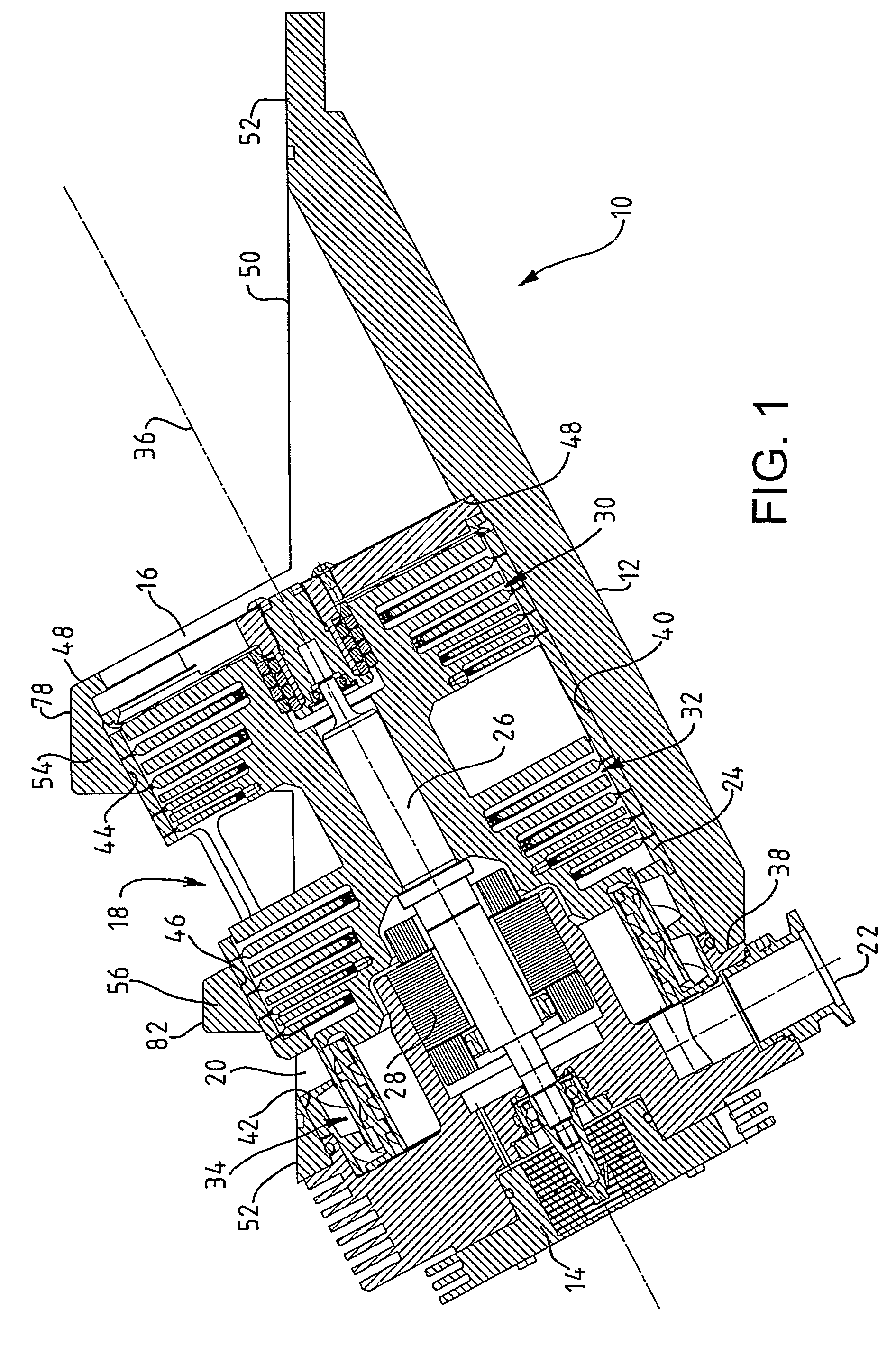
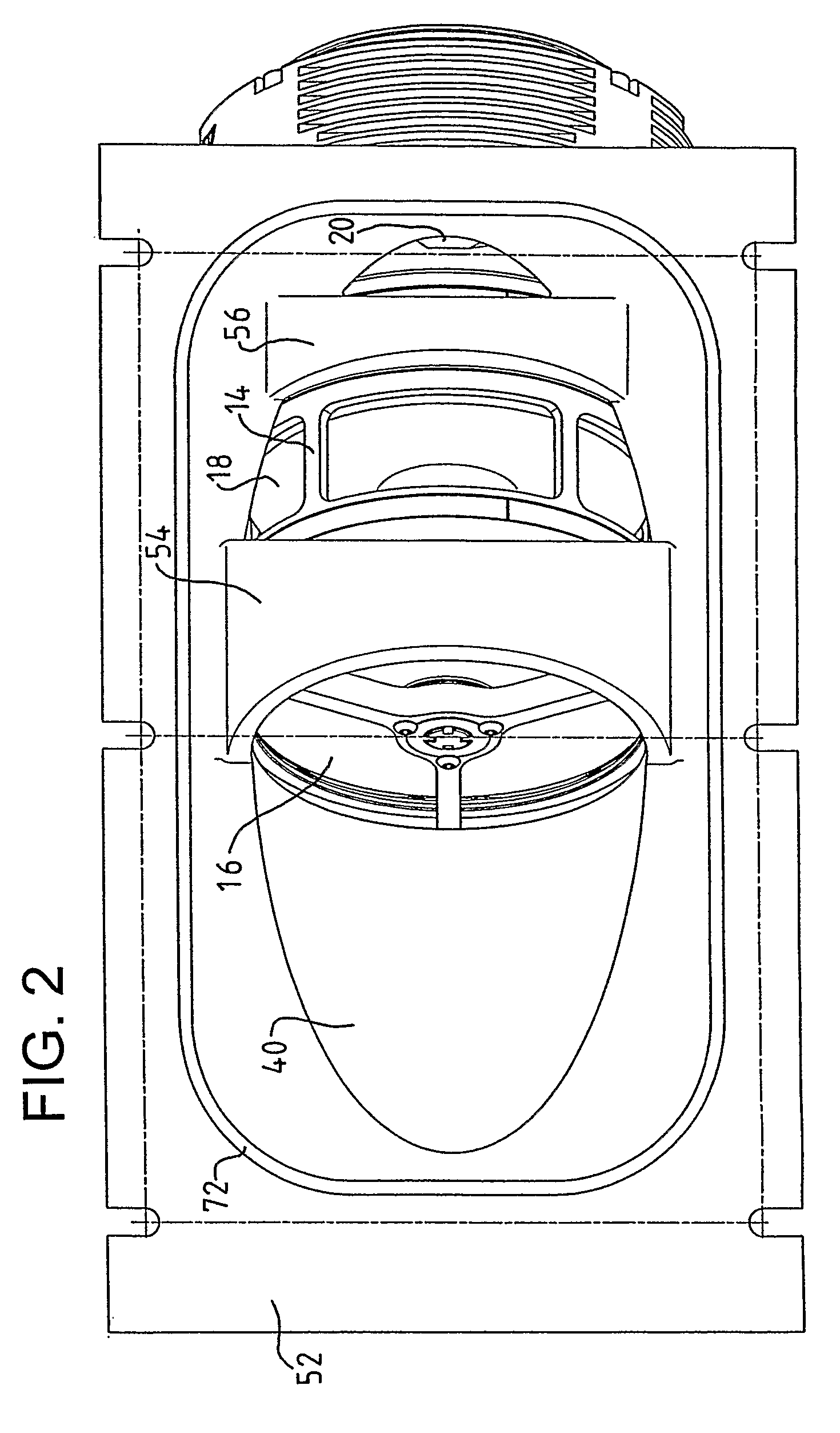
[0018]The pump 10 comprises a housing 12 having a bore for receiving a cylindrical cartridge 14 containing a pumping mechanism and a plurality of fluid inlets 16, 18, 20 and a fluid outlet 22.

[0019]With reference to FIG. 1, the cartridge 14 comprises a multi-component body 24 within which is mounted a drive shaft 26. Rotation of the shaft 26 is effected by a motor 28 positioned about the shaft 26. The shaft 26 is mounted on opposite bearings. For example, the drive shaft 26 may be supported by a hybrid permanent magnet bearing and oil lubricated bearing system.

[0020]The pumping mechanism within the cartridge includes at least three pumping sections 30, 32, 34. The first pumping section 30 comprises a set of turbo-molecular stages. In the example shown in FIG. 1, the set of turbo-molecular stages 30 comprises four rotor blades and four stator blades of known angled construction. In this example, the rotor blades of the first pumping section are integral with the drive shaft 26.

[0021]...


PUM


Abstract

A differentially pumped mass spectrometer system comprises a mass spectrometer having first and second pressure chambers through which, during use, ions are conveyed along a path. A pump assembly (10) for differentially evacuating the chambers (62, 66, 68) is attached to the mass spectrometer. The pump assembly comprises a housing (12) attached to the mass spectrometer and a cartridge (14) inserted into the housing. The cartridge has a plurality of inlets (16, 18, 20) each for receiving fluid from a respective pressure chamber (62, 68, 66) and a pumping mechanism (30, 32, 34) for differentially pumping fluid from the chambers. The cartridge is inserted into the housing such that the pumping mechanism (10) is inclined relative to the ion path (76), but with the cartridge protruding into the mass spectrometer to such an extent that at least one of the inlets (16, 18) at least partially protrudes into its respective chamber (62, 68) without crossing the ion path.

Description

FIELD OF THE INVENTION[0001]This invention relates to a vacuum pump, and in particular to a vacuum pump with multiple inlets suitable for differential pumping of multiple chambers.BACKGROUND OF THE INVENTION[0002]There are a number of types of apparatus where a plurality of chambers or systems need to be evacuated down to different levels of vacuum. For example, in well known types of mass spectrometer, the analyser / detector has to be operated at a relatively high vacuum, for example 10−5 mbar, whereas a transfer chamber, through which ions drawn and guided from an ion source are conveyed towards the detector, is operated at a lower vacuum, for example 10−3 mbar. The mass spectrometer may comprise one or more further chambers upstream from the analyser chamber, which are operated at progressively higher pressures to enable ions generated in an atmospheric source to be captured and eventually guided towards the detector.[0003]Whilst these chambers may be evacuated using separate turb...

Claims


Application Information

Patent Timeline
Patent Type & Authority Patents(United States)
IPC IPC(8): F04B25/00F04D1/06F04D31/00F04D19/04F04D29/60G01M3/20
CPCF04D19/042F04D29/601G01M3/205H01J49/24
Inventor STUART, MARTIN NICHOLASGOODWIN, DAVID JOHNOLSEN, IAN
Owner EDWARDS LTD
Why Eureka
Try Eureka