Multi-refrigerator high speed cryopump

a cryopump and multi-refrigerator technology, which is applied in the direction of positive displacement liquid engine, domestic cooling apparatus, separation process, etc., can solve the problems of increasing the cool down time and regeneration time of the cryopump, adding both weight and cost, and achieving high pumping speed , the effect of improving the refrigeration capability and overall efficiency

Active Publication Date: 2013-08-15
EDWARDS VACUUM LLC
View PDF26 Cites 9 Cited by
  • Summary
  • Abstract
  • Description
  • Claims
  • Application Information

AI Technical Summary

Benefits of technology

[0014]Certain embodiments of the invention allow for improved refrigeration capability and overall efficiency of extended size cryopumps (e.g., more than 500 mm) used in a high vacuum environment where high pumping speed is required. One advantage is uniform temperature distribution across the frontal array through controlled heat leakage via a thermal coupling onto the first stage of a two-stage refrigerator. Other advantages are uniform frost growth and mechanical rigidity of the extended size radiation shield / first stage. Embodiments may use two radially placed heat sinks Optimized heat conductance rods may allow for more efficient use of available refrigeration to conduct heat from the pump's mouth to its base. The thermal conductance rods can be designed to carry sufficient heat for an extended size cryopump (more than 500 mm), and to have no interference with the frost growing on the second stage array, therefore allowing reduced or minimal degradation of pumping speed, as well as reduced or minimal impact on the system's overall weight. The cooling of the rods may be accomplished through a first stage base plate, cooled by two refrigerators, e.g., by a single-stage refrigerator unit and a two-stage or other multi-stage refrigerator unit.

Problems solved by technology

This increased mass of the shielding adds both weight and cost to the product and disadvantageously increases the cool down time and regeneration time of the cryopump.

Method used


Image

  • Multi-refrigerator high speed cryopump
  • Multi-refrigerator high speed cryopump
  • Multi-refrigerator high speed cryopump

Examples


Embodiment Construction

[0022]A description of example embodiments of the invention follows.

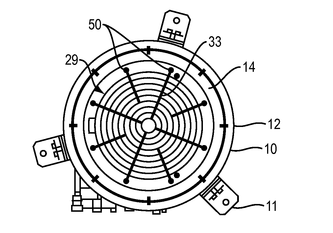
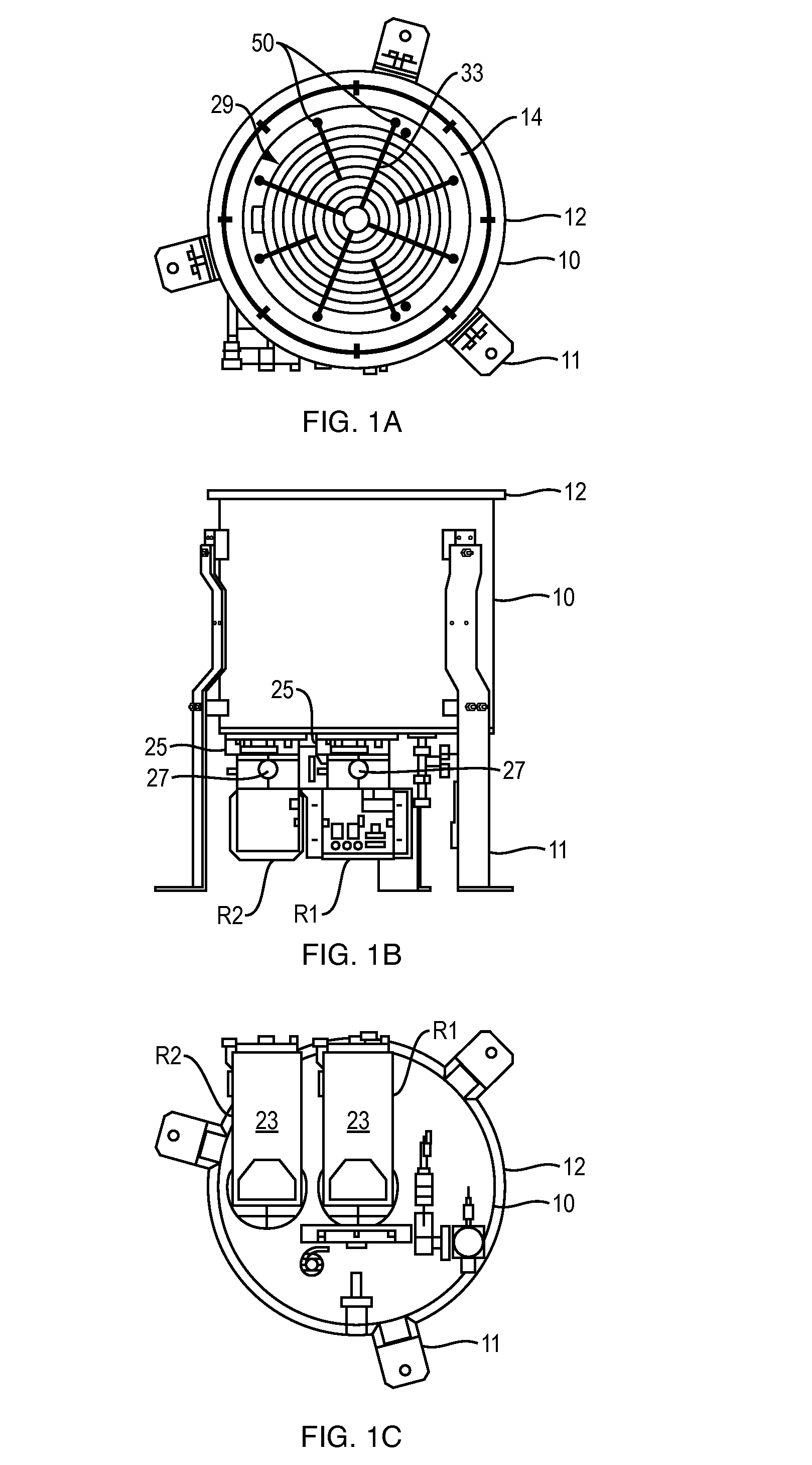
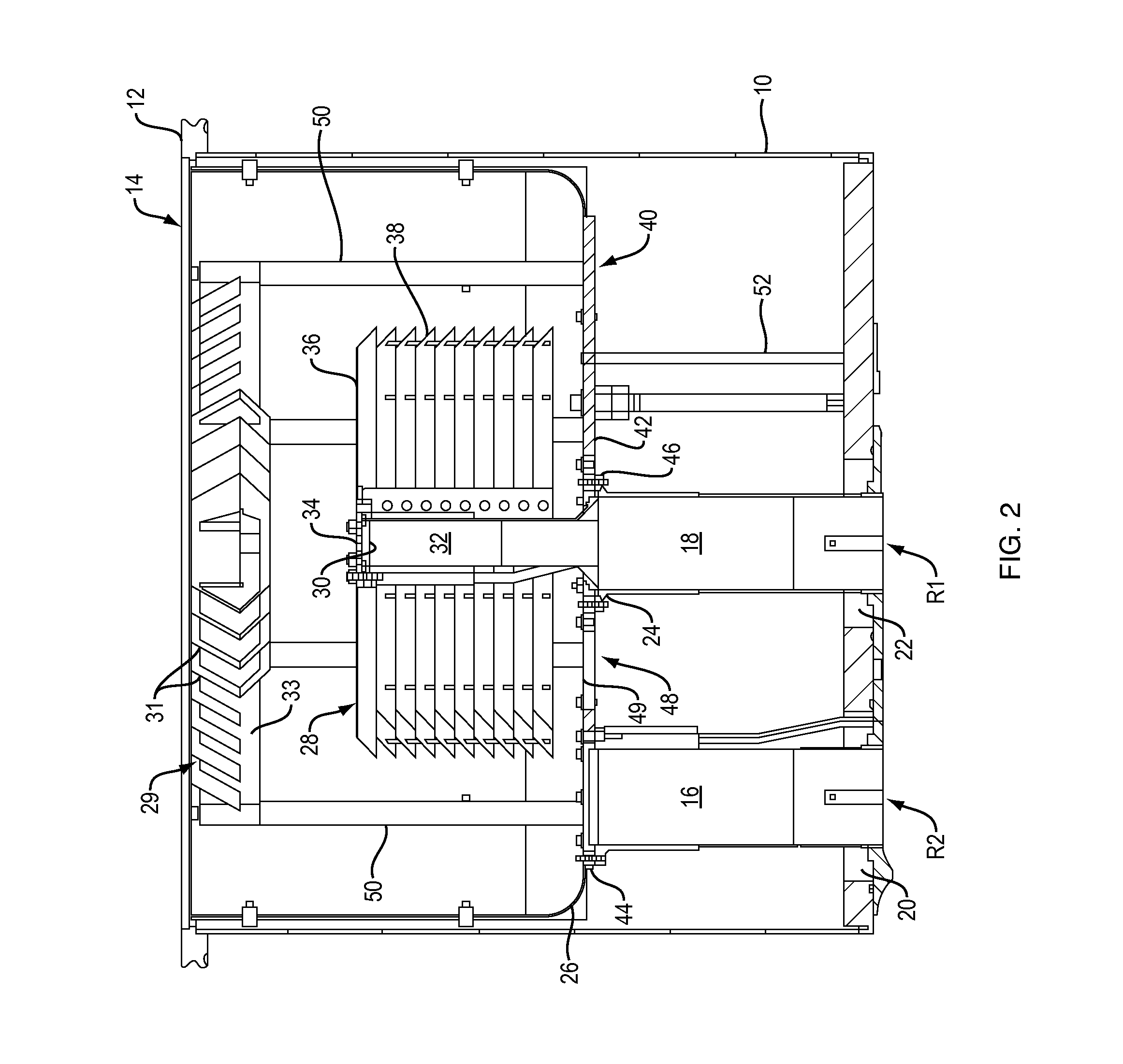
[0023]This invention relates to improvements of operational parameters of refrigeration systems, such as closed-loop cryogenic systems used as a refrigeration source for cryopumps. Such closed-loop refrigerators and cryopumps are described in U.S. Pat. No. 2,966,035 to W. Gifford et al., and U.S. Pat. No. 3,338,063 to W. Hogan et al. Cryopumps based on available closed-loop cryogenic refrigerators are typically limited in size to an inlet diameter of about 0.3 meters. With increased demand on the pumping speed, the inlet diameter of a cryopump needs to be made larger, thus rapidly increasing the total surface area of the cryoarray. Increased area of the cryoarray leads to higher thermal load. At some point, the limit of the cryogenic refrigerator is reached and further increase of the pump's size cannot be achieved without additional refrigeration. One approach is the use of additional refrigerators which allows the...


PUM

PropertyMeasurementUnit
temperatureaaaaaaaaaa

Abstract

A refrigerator system or cryopump includes a first refrigerator having at least first and second stages, and a second refrigerator. A thermal coupling between the first stage of the first refrigerator and a cold end of the second refrigerator is restricted to maintain a temperature difference between the cold end of the second refrigerator and the first stage of the first refrigerator. The refrigerator system or cryopump also includes a radiation shield in thermal contact with the cold end of the second refrigerator, and a condensing surface, spaced from and surrounded by the radiation shield, and in thermal contact with a second stage, e.g., coldest stage, of the first refrigerator. The restricted thermal coupling can be configured to balance the cooling load on the two refrigerators.

Description

RELATED APPLICATION[0001]This application is a continuation of International Application No. PCT / US2011 / 045977, which designated the United States and was filed on Jul. 29, 2011, published in English, and which claims the benefit of U.S. Provisional Application No. 61 / 369,133, filed on Jul. 30, 2010. The entire teachings of the above applications are incorporated herein by reference.BACKGROUND OF THE INVENTION[0002]Cryopumps currently available are typically used in equipment for the manufacture of integrated circuits and other electronic components, as well as for the deposition of thin films in a variety of consumer and industrial products. The utility of the cryopumps is to create a contaminant-free vacuum by freezing or adsorbing gases from a work environment.[0003]The design concepts of these cryopumps are similar. The cryopumps comprise a low temperature surface called a primary pumping surface, which operates in the temperature range of 4 to 25 Kelvin (K) and a higher tempera...

Claims


Application Information

Patent Timeline
Patent Type & Authority Applications(United States)
IPC IPC(8): B01D8/00
CPCF04B37/08F04B37/14B01D8/00F25D19/006F25B9/10F25B7/00
Inventor BARTLETT, ALLEN J.EACOBACCI, JR., MICHAEL J.SYSSOEV, SERGEI
Owner EDWARDS VACUUM LLC
Why Eureka
Try Eureka