Supercharge Your Innovation With Domain-Expert AI Agents!

High-pressure tank, vehicle including high-pressure tank, and method for manufacturing high-pressure tank

a technology of high-pressure tanks and tanks, which is applied in the direction of electrochemical generators, container discharge methods, other domestic articles, etc., can solve the problems of complex manufacturing process and increase manufacturing costs

Active Publication Date: 2022-11-01
TOYOTA JIDOSHA KK
View PDF14 Cites 0 Cited by
  • Summary
  • Abstract
  • Description
  • Claims
  • Application Information

AI Technical Summary

Benefits of technology

The patent aims to provide a better way of manufacturing high-pressure tanks with a protective layer that is easier to check on and increases the protectiveness of the fiber layer. The current process of manufacturing can be complicated and increase costs. The patent proposes a new method to address this issue.

Problems solved by technology

Therefore, the process for manufacturing the high-pressure tank may be complicated, or manufacturing costs may increase.

Method used


Image

  • High-pressure tank, vehicle including high-pressure tank, and method for manufacturing high-pressure tank
  • High-pressure tank, vehicle including high-pressure tank, and method for manufacturing high-pressure tank
  • High-pressure tank, vehicle including high-pressure tank, and method for manufacturing high-pressure tank

Examples


first embodiment

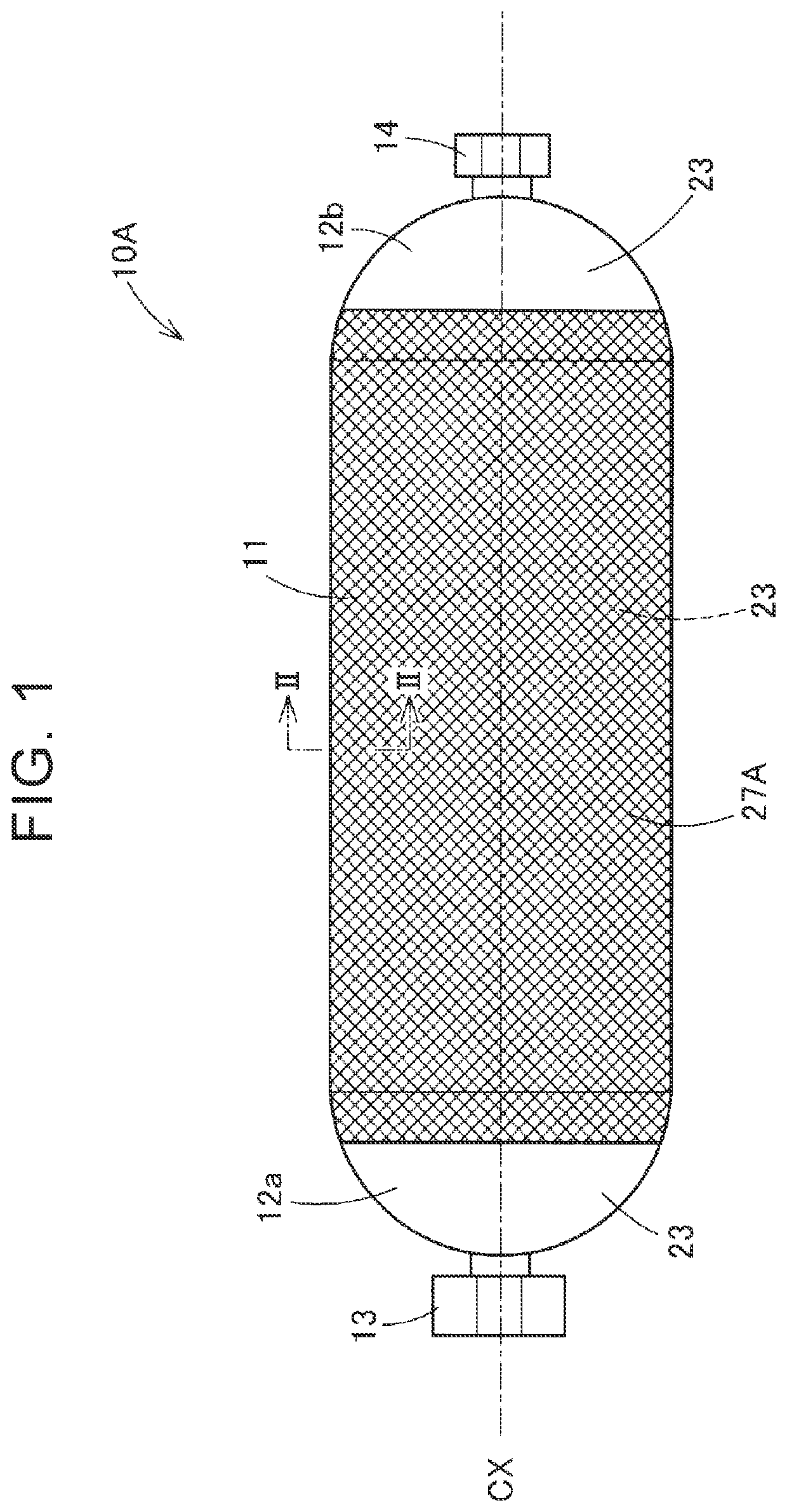
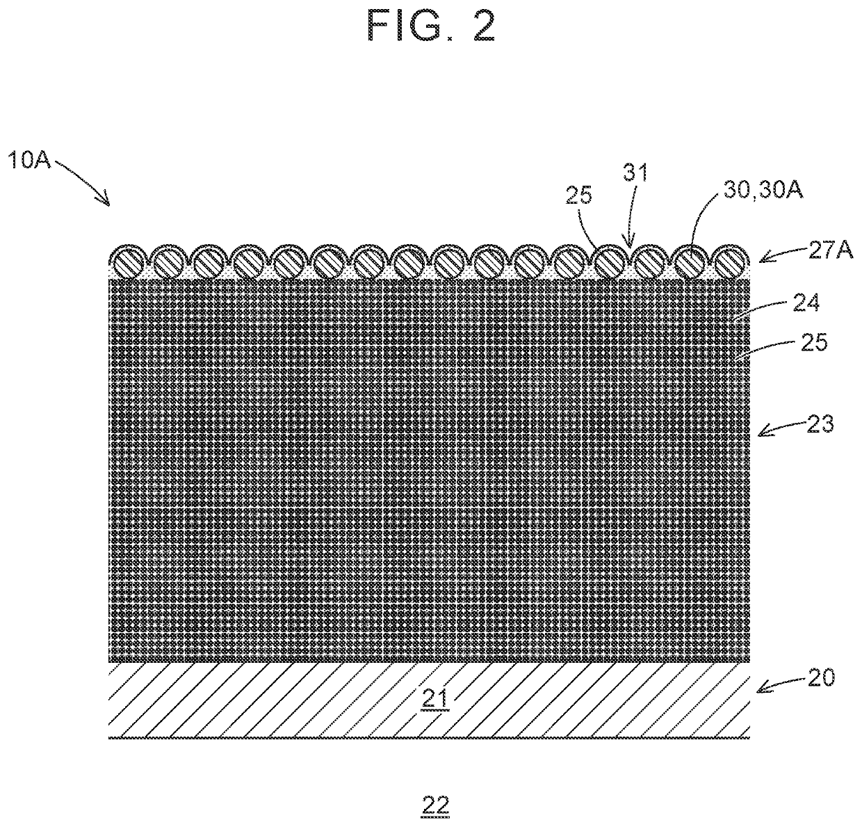
[0048]FIG. 1 is a schematic side view illustrating a high-pressure tank 10A of a first embodiment. In FIG. 1, a central axis CX of the high-pressure tank 10A is represented by a long dashed short dashed line. The high-pressure tank 10A is a hollow container that stores a fluid. In the first embodiment, the high-pressure tank 10A is mounted on a fuel cell vehicle, and is used for storing fuel gas to be supplied to a fuel cell. In the first embodiment, the high-pressure tank 10A is filled with hydrogen under high pressure as the fuel gas of the fuel cell. The high-pressure tank 10A has a pressure resistance of 70 MPa or higher.

[0049]The high-pressure tank 10A has a cylinder 11 that has a substantially cylindrical shape and domes 12a and 12b that have a substantially hemispherical shape and provided at respective ends of the cylinder 11. Each of the domes 12a and 12b has an opening (not illustrated) at the apex. The opening communicates with an internal space of the high-pressure tank ...

second embodiment

[0070]FIG. 10A is a schematic side view illustrating a high-pressure tank 10B of a second embodiment. FIG. 10B is a schematic sectional view of the high-pressure tank 10B cut along a line XB-XB in FIG. 10A. FIG. 10C is a schematic sectional view of the high-pressure tank 10B cut along a line XC-XC in FIG. 10B. The structure of the high-pressure tank 10B of the second embodiment is substantially the same as that of the high-pressure tank 10A of the first embodiment except that a protective layer 27B of the second embodiment is provided in place of the protective layer 27A described in the first embodiment.

[0071]As illustrated in FIG. 10A and FIG. 10B, the protective layer 27B of the second embodiment covers a part of the side face of the cylinder 11 in a range between the domes 12a and 12b at respective ends. The high-pressure tank 10B is mounted on the fuel cell vehicle in a posture in which the protective layer 27B is located on a lower side. As illustrated in FIG. 10B, the protect...

third embodiment

[0087]FIG. 14 is a schematic side view illustrating a high-pressure tank 10C of a third embodiment. The structure of the high-pressure tank 10C of the third embodiment is substantially the same as the structure of the high-pressure tank 10B of the second embodiment except that a sheet mesh member 30C of the third embodiment described below is used in place of the sheet mesh members 30B described in the second embodiment. A protective layer 27C of the third embodiment is formed by the thermosetting resin 25 entering the pores 31 of a single sheet mesh member 30C.

[0088]FIG. 15 is a schematic perspective view illustrating the structure of the sheet mesh member 30C. The sheet mesh member 30C of the third embodiment is made of an expanded metal similarly to the sheet mesh member 30B of the second embodiment, but differs from the sheet mesh member 30B of the second embodiment in terms of the opening shapes of the pores 31. In the sheet mesh member 30C, each of the threads 33 enclosing the...


PUM

PropertyMeasurementUnit
widthaaaaaaaaaa
pressureaaaaaaaaaa
thicknessaaaaaaaaaa

Abstract

A high-pressure tank includes a liner, a fiber layer, and a protective layer. The liner has an internal space to store a fluid. The fiber layer includes fibers wound around an outer surface of the liner, and a thermosetting resin that has been cured and covers surfaces of the fibers. The protective layer includes a porous member disposed on the fibers, the porous member having a plurality of pores extending through the porous member in a thickness direction of the porous member. The thermosetting resin has entered the pores.

Description

INCORPORATION BY REFERENCE[0001]The disclosure of Japanese Patent Application No. 2019-194366 filed on Oct. 25, 2019 including the specification, drawings and abstract is incorporated herein by reference in its entirety.BACKGROUND1. Technical Field[0002]The present disclosure relates to a high-pressure tank, a vehicle including the high-pressure tank, and a method for manufacturing the high-pressure tank.2. Description of Related Art[0003]There is a high-pressure tank having a fiber layer including fibers wound around the surface of a liner, and a thermosetting resin that is thermally cured. For example, Japanese Unexamined Patent Application Publication No. 2018-100768 (JP 2018-100768 A) discloses a high-pressure tank having a reinforcing layer formed of the fiber layer, and a protective layer made of a glass fiber reinforced plastic and formed on the reinforcing layer. With the glass fiber reinforced plastic, the protective layer can be formed to have a high shock resistance. Ther...

Claims


Application Information

Patent Timeline
Patent Type & Authority Patents(United States)
IPC IPC(8): F17C1/06F17C1/16F17C13/08
CPCF17C1/06F17C1/16F17C13/084F17C2201/0109F17C2203/0604F17C2203/0663F17C2270/0184F17C1/005B60K15/07B29C70/84F17C2221/012F17C2265/066F17C2223/036F17C2201/056F17C2203/0621F17C2203/012F17C2221/033F17C2203/0646F17C2203/066F17C2203/067F17C2209/219F17C2209/2145F17C2209/2163F17C2209/232F17C2205/0103F17C2205/0196B29L2031/712F17C2201/058F17C2203/0673F17C2209/2154F17C2223/0123F17C2203/0685F17C2203/069F17C2223/0161Y02E60/32
Inventor FUJII, MANABU
Owner TOYOTA JIDOSHA KK
Features
  • R&D
  • Intellectual Property
  • Life Sciences
  • Materials
  • Tech Scout
  • Unparalleled Data Quality
  • Higher Quality Content
  • 60% Fewer Hallucinations
Learn More