High carbon content cobalt-based alloy

a cobalt-based alloy, high carbon content technology, applied in the field of cobalt-based alloys, to achieve the effects of reducing the toughness of macro fractures, reducing the content of cr, and reducing the thickness of the material

Active Publication Date: 2022-11-08
VBN COMPONENTS
View PDF20 Cites 1 Cited by
  • Summary
  • Abstract
  • Description
  • Claims
  • Application Information

AI Technical Summary

Benefits of technology

[0140]One advantage of the present invention is that it does not require the use of any organic binders or adhesives and therefore the 3D-printed product usually comprises a combined content of carbon, tungsten, chromium and cobalt which is equal to or greater than 95 weight %. In one embodiment of the invention the combined content of carbon, tungsten, chromium and cobalt is equal to or greater than 97 weight %. Preferably the combined content of carbon, tungsten, chromium and cobalt is equal to or greater than 98 weight %. More preferably the combined content of carbon, tungsten, chromium and cobalt is equal to or greater than 99 weight %. Most preferably the combined content of carbon, tungsten, chromium and cobalt is equal to or greater than 99.9 weight %. In one embodiment of the invention the amount of organic compounds in the 3D-printed product is equal to or less than 0.1 wt %. Preferably the amount of organic compounds in the 3D-printed product is equal to or less than 0.05 wt %. In one embodiment of the invention the product is essentially free from any organic compounds. The carbon in the product is mainly in form of carbides such as tungsten and chromium carbides, but elemental carbon and elemental tungsten can also be present in the matrix.
[0141]Metal compounds that contain carbides sometimes suffer from that carbides forms clusters, dendritic or net structures which makes the material more brittle. Typically in these types of alloys, especially with high Cr (˜30 wt %) and C (˜2.5 wt %) content or more, Cr forms carbides (such as Cr7C3 and Cr23C6 but also other stochiometric types). These carbides typically grow quickly in solidification stage which results in large and long stringers with dimensions from 100-1000 μm in size see FIGS. 6 to 11. These large and sharp formed carbides result in stress concentration and reduce the macro fracture toughness, thermal shock and fatigue resistance in the material. Therefore, one of the advantages of the present invention is that the 3D-product contains carbides grains or particles that are in general smaller than those found in the prior art and are well-dispersed in the matrix. This is achieved by on the one hand reducing the Cr content and on the other hand using the additive manufacturing technology to ensure a very rapid solidification rate.
[0142]The multiphase alloy comprises a matrix of mainly cobalt but also chromium, tungsten and carbon. There are carbides of chromium and tungsten, CrC-types and WC, present in the matrix. The chromium carbides may surround the tungsten carbides which in turn are surrounded by the matrix.
[0143]One advantage of the present invention is the achievement of improved mechanical properties of the 3D-printed product. The hardness of the product, after HIP, may be at least 700 HV, such as at least 750 HV, or at least 800 HV, or at least 850 HV, or at least 870 HV. In one embodiment the hardness is 800-950 HV or 850-900 HV. The HIP process was done by keeping the product at 1120-1160° C. for 3 hours at 1000 bar (100 MPa). In one embodiment the hardness prior to HIP is 970-1000 HV2 kg. The hardness was determined by using 2 kg Vickers indention, according to standard SS-EN ISO 6507. Additionally the fracture toughness measured as total crack length, i.e. the sum of the up to four cracks formed at the corners of the diamond-shaped indentation using a 250 kg Vickers indent at room temperature, is very high and the crack length may be as short as 350 μm or less, or 300 μm or less, or 250 μm or less, or 150 μm or less, or 100 μm or less, or 50 μm or less, or 30 μm or less, or 10 μm or less. In one embodiment no cracks were formed. The crack length was determined using Palmqvist fracture toughness method but with a higher load (250 kg) and only presented here as the sum of the crack lengths not as a K1c value. The indentation is performed three times and at three different places on the sample and the average of the sums of the crack lengths is presented. The reason to use a higher load is that at lower loads often no cracks were formed and therefore no value for the toughness could be obtained. The crack length indentation tests were performed on cross section samples, ground and polished in steps down to 1 μm diamond suspension in the same way as in the hardness standard ASTM E384-16. Many of the alloys or products according to the present invention do not form any cracks at all during the tests. However, the fracture toughness at high temperature such as 750° C. or 800° C. is very difficult to measure, but it is well known that crack initiation occurs at the maximum stress point which is set by the largest “error” or “imperfection” in the material. In alloys such as described in this invention, this largest “error” or “imperfection” is the biggest carbide.
[0144]Without being bound by theory but the mechanical properties of the present invention is believed to be a result of the fine microstructure of the product. The 3D-printed product is essentially free from dendritic structures of carbide grains and instead the carbides are essentially spherical or round. The carbide grains are small in size and they are evenly distributed within the matrix as seen in the figures. The alloy of the 3D-printed product usually does not comprise any carbides having a size equal to or larger than 30 μm, preferably not larger than 20 μm, or not larger than 10 μm. In one embodiment the maximum carbide size is 5 μm. Still the total amount of carbides in the printed material is very high, at least 50 vol % of the area, or at least 60 vol %, or at least 65 vol %. In one embodiment the total amount of carbides is 65-70 vol % such as around 68 vol %. The total amount of carbides in a sample is determined using SEM. A sample surface is selected which is believed to be representable of the product. The edge of each carbide is marked and from which the total carbide area is calculated using any suitable software. FIG. 25-27 shows an example where carbide edges have been marked. The volume fraction of the carbide is then translated from the calculated area. The average area of the carbides may be 5 μm2 or less, such as 3 μm2 or less. In these figures, the carbide areas and size are not calculated since it is difficult to see the
[0145]Not only does the present invention facilitate the preparation of products and components that have improved mechanical properties which may withstand corrosion, it also makes it possible to prepare products with advanced or complex three-dimensional shapes and forms. The product may comprise cavities, channels or holes and the product may have curved portions or spiral forms. These shapes or forms are prepared without any removal of the alloy besides any optional after treatments. The cavities, holes or channels may be curved, that is to say that their surfaces may be curved, helical or spiral or the like. In some embodiments the product contains cavities where the cavities are sealed or have an opening wherein the diameter or width of the opening is less than the diameter or width of the underlying cavity. The product may be a cutting tool such as a milling cutter, shaper cutter, power skiving cutter, drill, milling tool etc, or a forming tool such as extrusion head, wire drawing die, a hot rolling roll, etc., or wear components such as pumps or valve components, gliding or roll bearing rings, etc.

Problems solved by technology

All the methods have advantages and disadvantages, and the choice is dependent on conflicting demands when it comes to quality and cost.
“High purity” in these materials is usually synonymous with “low oxygen content” since in general the presence of oxygen results in oxide impurities which result in impaired properties of the material.
A major disadvantage with the common casting-ingot-technique is the long solidification times, resulting in coarse microstructures and solidification patterns.
With a long solidification time, the carbides will form carbide structures which significantly reduce the mechanical properties of the material.
A long solidification time will also result in a coarse microstructure in general, which also give impaired material properties.
Another disadvantage is the need of subsequent forging and forming of the ingot to a metal bar (which typically is the end product in the material-processing plant).
Forging and rolling are complex processes that require a number of heating and forming steps of the material ingot with resultant high energy losses.
Highly alloyed materials are typically very difficult to form, and therefore require very high temperatures and high loads, which could result in cracked ingots, as well as high process costs.
In other words, the fact that it must be possible to forge and / or to roll alloys made using this process limits the possibility of high alloying.
One disadvantage is that the surface oxygen on every powder particle will give a higher oxygen content compared to a solidified large ingot as the oxygen accumulates on all the powder particles in the atomizing process.
For PM-HIP of near-net-shape components, the need for capsule limits how complex a component can be.
An important limitation of the PM-HIP process is the difficulty of atomizing the powder.
Here, high melting temperatures and strong carbide formers limit the possibility to get a continuous industrial atomization process for larger batches.
In addition, high melting temperature are expensive to achieve and difficult to handle in an industrial scale in the melting furnace (crucibles).
But the resulting material still needs to be wrought by heating, forging and rolling to become a metal bar with the required dimensions.
This is typically difficult for highly alloyed materials and, if even if it is possible, the resulting yield is sometimes low.
Again, the need to be able to forge and / or roll the material limits the possibility for high alloying.
Another problem with highly alloyed materials is that they also are difficult and expensive to machine and a lot of the expensive highly alloyed material is wasted during machining.
The higher the wear resistance and hardness of an alloy, the more difficult it is to machine.
The group of CoCr alloys is well known to be very difficult to machine and the hard, high carbon grades are almost only possible to shape by grinding.
The disadvantages with casting are the formation of a coarse microstructure and solidification patterns due to long solidification times and the anisotropy in the component due to different solidification times at different sections.
Furthermore, casting methods require a mold which sets the limit for how complex a component can be.
In addition, the potential complexity of a desired component must be heavily reduced due to the need for quick and uniform cooling speed, and the brittleness of the material.
Despite all these efforts, often the cooling rates are not fast enough to reduce the chromium carbide sizes.
The major disadvantages are: the size of the component changes during binder removal and diffusion, the need for compaction methods (pressing tools), the need of a binder and the removal of the binder (purity issues), limitations on the thickness or size of the product and porosity problems.
This large reduction in size during sintering and the resulting tolerance issues, and the constraints in component size, cause major problems.
However, the sintering techniques require some kind of pre-consolidation of a metal powder mixture and a binder / pressing.
However, AM process needs powders that can be granulated, and this is not possible on an industrial scale for every alloy composition.
High carbon materials tend to crack when used in additive manufacturing processes where the materials are melted layer by layer and special care has to be taken to achieve a successful run.
Still prior art have not shown 3D printing of steels or other alloys with high carbon or carbide content and high tungsten content.
Cobalt chromium alloys are resistant to corrosion due to the formation of a protective layer, exhibit good mechanical properties, good wear resistance and are also biocompatible.
The big problem is that these types of materials are very difficult, or even impossible, to machine.
However, very quick solidifying upon a cold substrate leads to large stresses and therefore the range of materials that could be used in such coating is limited.
Other typical limitations in cladding methods are the lack of control of the ongoing cladding process.
It is possible to use a high carbon cobalt chrome alloy powder for consolidation in the HIP, but it is only possible to produce small parts with limited mechanical properties.
However there is a major risk that the component cracks during cooling due to the low fracture toughness.
There is therefore a large gap in the prior art between the need for CoCr-materials with high C content with excellent mechanical and thermal properties and the existing alloy compositions and manufacturing methods.
However, this patent fails to disclose an alloy or a 3D printed product with both high carbon and tungsten content.

Method used


Image

  • High carbon content cobalt-based alloy
  • High carbon content cobalt-based alloy
  • High carbon content cobalt-based alloy

Examples


example 1

[0164]Prior Art Market Study

[0165]In order to determine the alloying content and microstructure of the group of conventional, commercially-available cast high carbon cobalt chromium alloys, a market analysis was performed, wherein the composition and microstructure of a number of real material pieces were analyzed, see FIG. 5.

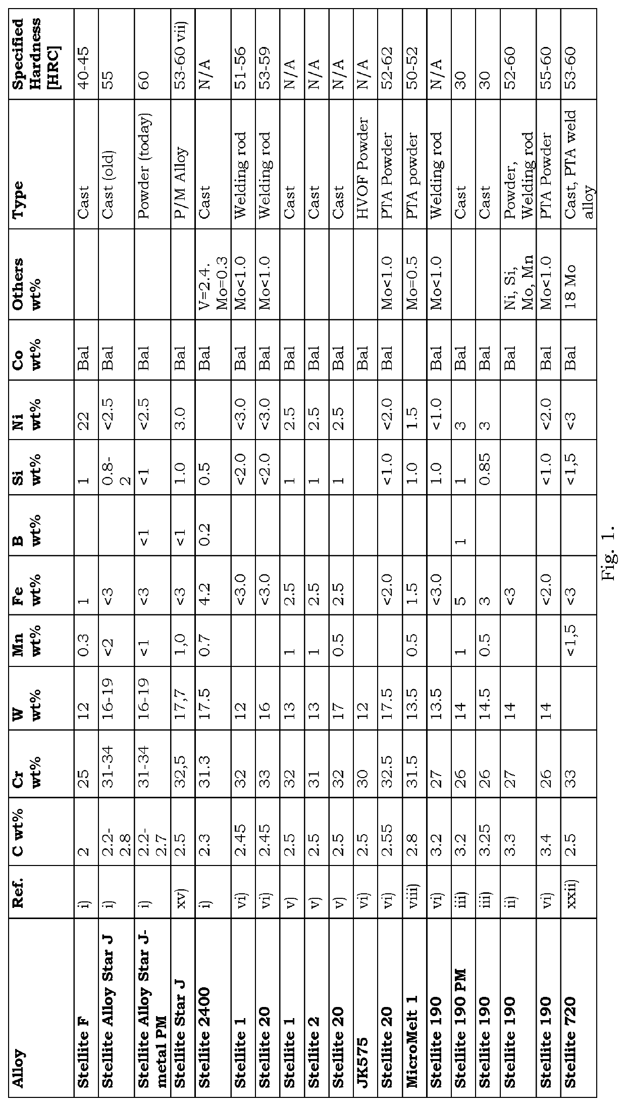
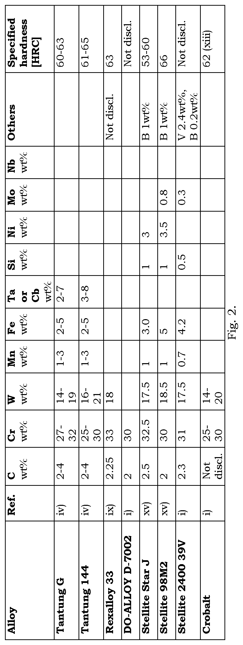
[0166]Note that the Tantung analysis specification shown in FIG. 2 is extremely wide—two alloys with 2 wt % and 4 wt % C are extremely different in nearly every mechanical property. This is assumed to be a result of traditional casting techniques, where the content is not able to be controlled very accurately and therefore the properties of all alloy combinations in this wide specification are unknown. In addition, as will be shown here, in no case is the C content as high as the maximum amount specified in FIG. 2.

[0167]An important result, seen in FIG. 5. is that the actual carbon content in these types of cast alloys is generally 2.45 wt % or lower. This is a...

example 2

[0191]Two types of alloys were 3D printed according to the present method.

[0192]MicroMelt1 (MM1), existing PTA grade from Carpenter having the composition of:

[0193]

CCrWNiMoFeSiMnCo2.831.513.51.50.51.51.00.5rest

[0194]Composition of an alloy according to the present invention with the composition of:

[0195]

CCrWNiMoFeSiMnCo3.9520.621.20.7rest

[0196]The samples were tested and analyzed regarding hardness and micro structure.

[0197]On the Micro Melt 1-alloy after 3D-printing, the hardness was measured to 835 HV2 kg, which is about 65 HRC. In the specification from Carpenter*, a typical deposited hardness of the same alloy is 50-52 HRC. *=Plasma Transferred Arc (PTA) and Laser Overlay powder specification, Carpenter Powder Products, 07-12 1K T35E.

[0198]However, in the Micro Melt 1-alloy after 3D-printing, the microstructure still has a problem with Cr-carbides, forming longer sharp stringers / rods, which is locally increasing the stresses and therefore reducing the toughness in the materials....

example 3

[0206]The 3D printed product obtained in Example 2 with an alloy according to the present invention was tested in a long term heating test where the product was heated during an extended period of time and then the mechanical properties were tested.

[0207]The test was done by placing the product in an oven at 650° C. for 168 h, i.e. 7 whole days. This corresponds to a use time for a cutting tool of 75 seconds per gear when producing 800 gears, i.e. 6000 seconds (16.67 h). If the cutting tool is resharped ten times it will be 166.7 h.

[0208]The hardness of the product was 870 HV2 kg (around 66HRC) after HIP. After the long term heating test it was 866 HV2 Kg (around 66HRC). In other words, the hardness of the material is maintained even after long term use.

[0209]The same was seen for the melt trial alloy 6. After HIP it was 900 HV2 kg (around 67HRC) and after the long term heating test it was 870 HV2 kg (around 66HRC).


PUM

PropertyMeasurementUnit
melting pointaaaaaaaaaa
mean sizeaaaaaaaaaa

Abstract

The present invention relates to a 3D-printed cobalt-based alloy product comprising carbon, tungsten and chromium with very good mechanical and thermal properties as well as a method of preparing the 3D-printed product and a powder alloy. The alloy has a high carbon content leading to high carbide content but small and evenly distributed carbides. A method facilitating 3D printing of high carbide content alloys such as the present alloy is also disclosed.

Description

CROSS-REFERENCE TO RELATED APPLICATION[0001]This application claims priority to and is a 35 U.S.C. § 371 national phase application of PCT / SE2018 / 050251 (WO2018 / 169477), filed on Mar. 14, 2018 entitled “HIGH CARBON CONTENT COBALT-BASED ALLOY”, which application claims priority to and the benefit of Sweden Patent Application Nos. 1750298-0, filed Mar. 14, 2017, 1750299-8, filed Mar. 14, 2017 and 1750300-4, filed Mar. 14, 2017, the disclosures of which are incorporated herein by reference in their entirety.FIELD OF THE INVENTION[0002]The present invention relates to cobalt-based alloys, a 3D-printed product comprising one or more of said alloys and a method of preparing a 3D-printed product comprising one or more of said alloys.BACKGROUND[0003]Material Processing Techniques[0004]There are today a number of different manufacturing methods for obtaining high alloyed materials with high carbon content. All the methods have advantages and disadvantages, and the choice is dependent on conf...

Claims


Application Information

Patent Timeline
Patent Type & Authority Patents(United States)
IPC IPC(8): B32B15/00C22C19/07B33Y10/00B33Y70/00B23K15/00C22C30/00C22C32/00B22F1/05B22F1/065B33Y30/00B33Y80/00
CPCC22C19/07B22F1/05B22F1/065B23K15/0086B33Y10/00B33Y70/00C22C30/00C22C32/0052B22F2301/15B33Y30/00B33Y80/00C22C1/10B22F2005/001B22F2998/10B22F10/64B22F10/28B22F10/66B22F10/32B22F10/362B33Y70/10Y02P10/25B22F9/082B22F12/13C22C1/1068
Inventor BESTE, ULRIK
Owner VBN COMPONENTS
Why Eureka
Try Eureka