
Firearm laser sight

Active Publication Date: 2022-11-08
DRAKE DUSTIN
View PDF1 Cites 0 Cited by
  • Summary
  • Abstract
  • Description
  • Claims
  • Application Information

AI Technical Summary

Benefits of technology

The patent describes various ways to adjust the optical properties of a laser sight to improve the quality of the projected image. By changing the position of the optical components or the distance between them, the spread over distance can be reduced or increased, resulting in a more stable and accurate image. Additionally, using a pulsing beam can reduce perceived shakiness of the image, and a sight pattern can be generated to reduce the spread over traveled distances. These technical effects enhance the overall performance of laser sights and make them useful for a wide range of applications.

Problems solved by technology

However, the use of laser beams causes the visibility of the beam of light to be problematic (e.g., too large, low brightness) at long distances.
Such sizing of a conventional laser dot, especially at long distances, may result in a user of the weapon having difficulty in finding the laser dot being projected from their weapon.
Further, in sights where multiple conventional laser dots are used, the dots become skewed on angled targets, especially at long distances.

Method used


Image

  • Firearm laser sight
  • Firearm laser sight
  • Firearm laser sight

Examples


Embodiment Construction

[0058]The following detailed description is merely exemplary in nature and is not intended to limit the described embodiments or examples of the application and uses of the described embodiments. As used herein, the word “exemplary” or “illustrative” means “serving as an example, instance, or illustration.” Any implementation described herein as “exemplary” or “illustrative” is not necessarily to be construed as preferred or advantageous over other implementations. All of the implementations described below are exemplary implementations provided to enable persons skilled in the art to make or use the embodiments of the disclosure and are not intended to limit the scope of the disclosure, which is defined by the claims. Furthermore, there is no intention to be bound by any expressed or implied theory presented in the preceding technical field, background, brief summary, or the following detailed description. It is also to be understood that the specific devices and processes illustra...


PUM


Abstract

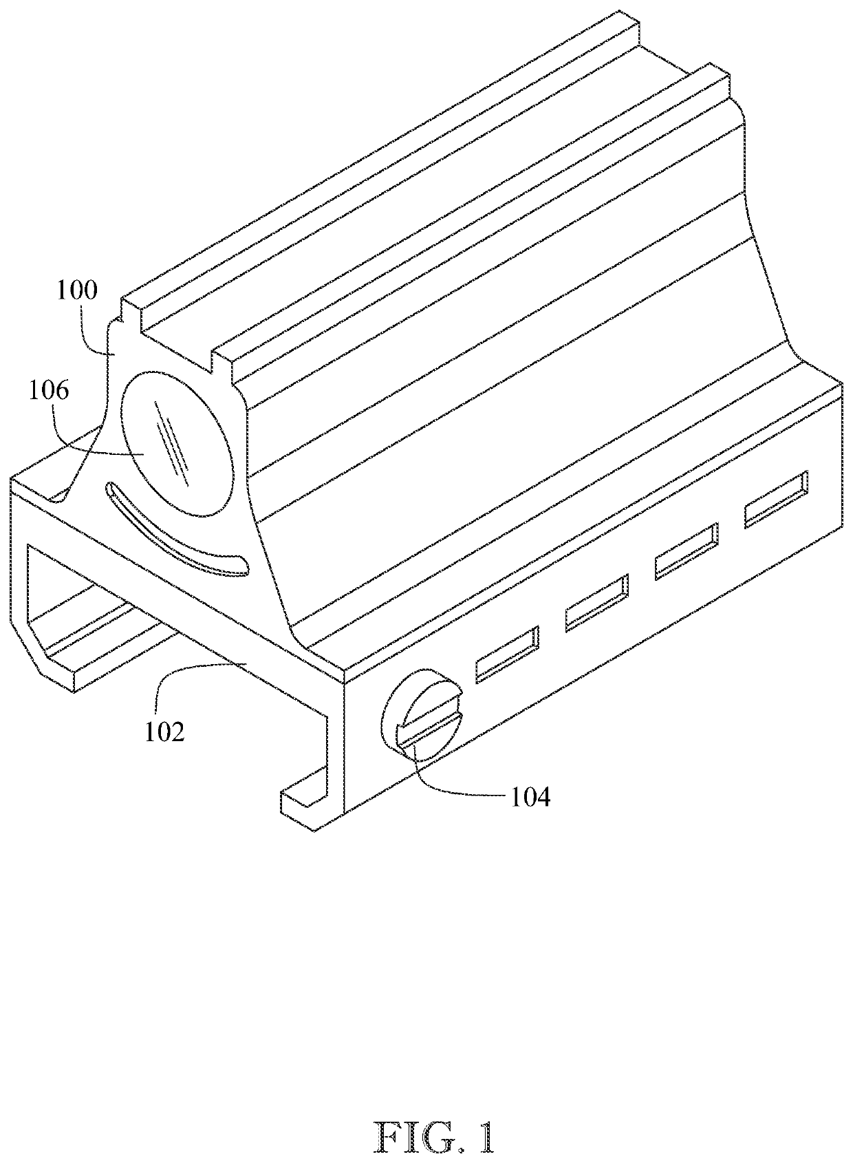
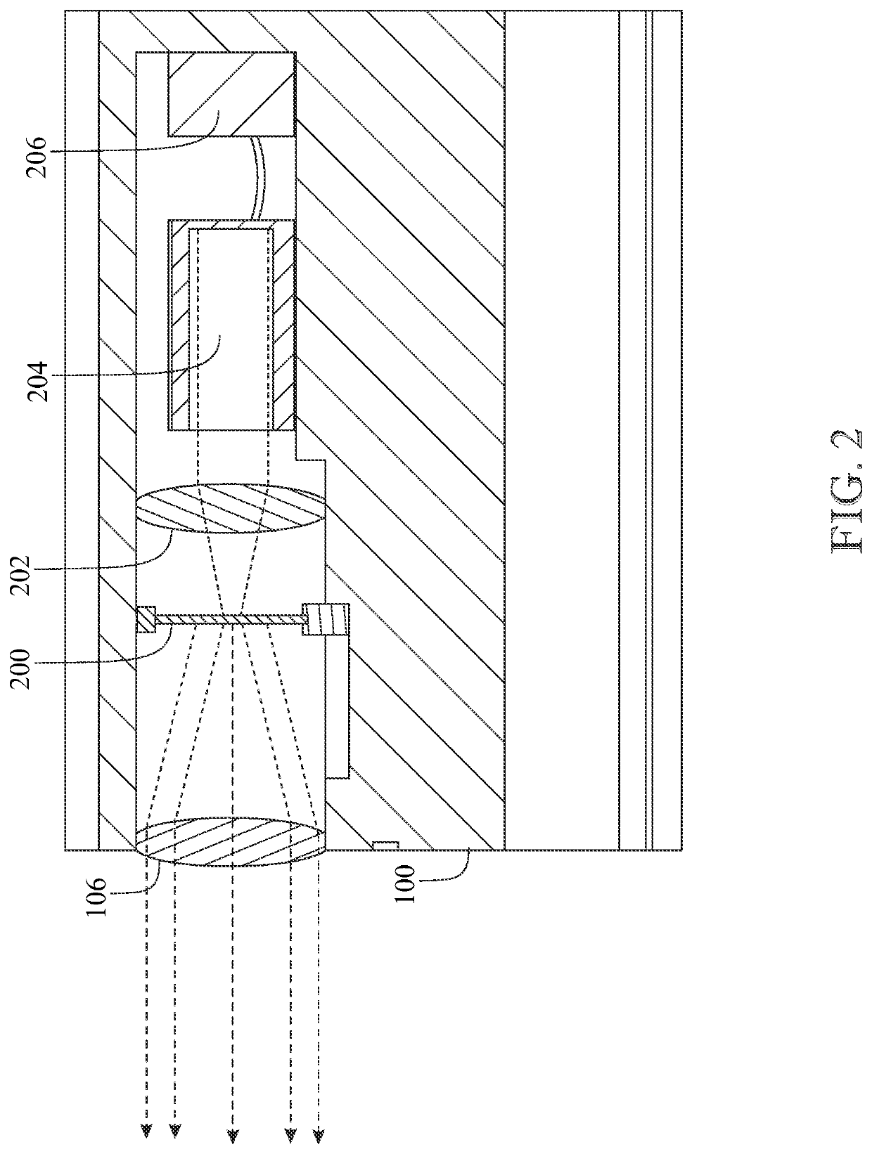
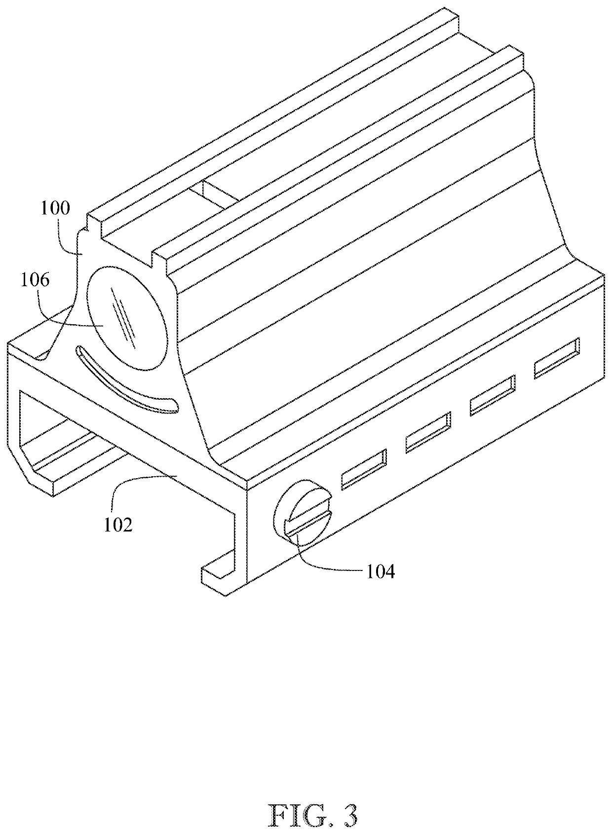
An improved firearm laser sight comprising a pattern generating element and an enlarging lens for enhanced projection of sight patterns onto an intended target is disclosed. The device is meant to be an accessory for firearms of all types by comprising any standardized methods for attachment, and may serve to decrease the time needed to acquire an intended target before firing. The device may implement a variety of sight patterns that may be projected larger and in a more pronounced way, when compared to standard firearm sights, to provide a clear image that may be quickly acquired even over longer distances. The improved firearm laser sight may be made available with a red or green visible laser, an infrared laser, or an ultraviolet light depending on the intended use of the device.

Description

CROSS-REFERENCE TO RELATED APPLICATION[0001]This application claims the benefit of co-pending U.S. patent application Ser. No. 16 / 517,555, filed Jul. 20, 2019, which claims the benefit of U.S. Provisional Patent Application Ser. No. 62 / 703,163, filed Jul. 25, 2018, each of which are incorporated herein in their entirety.FIELD OF THE INVENTION[0002]The present invention relates generally to firearms attachments, and more particularly, to an improved firearm laser sight.BACKGROUND OF THE INVENTION[0003]A firearm sight is an aiming device used to assist in visually aligning ranged weapons onto an intended target. One type of firearm sight is a reflector sight, or a reflex sight, which may be an optical device comprising a reflecting glass element and an illuminated projection of an aiming point superimposed on the field of view. One specific type of reflector sight is a red dot sight, which may be a non-magnifying sight comprising a light-emitting diode (LED) at the focus of collimatin...

Claims


Application Information

Patent Timeline
Patent Type & Authority Patents(United States)
IPC IPC(8): F41G1/14F41G1/34F41G1/36
CPCF41G1/14F41G1/345F41G1/36F41G1/35
Inventor DRAKE, DUSTIN
Owner DRAKE DUSTIN
Learn More