Method and system for mapping and locating a vehicle based on radar measurements

Active Publication Date: 2022-11-08
ROBERT BOSCH GMBH
View PDF37 Cites 0 Cited by
  • Summary
  • Abstract
  • Description
  • Claims
  • Application Information

AI Technical Summary

Benefits of technology

[0007]Based on the comparison between the aggregated measurement data and the already existing aggregated measurement data, the aggregated measurement data are optimized by reducing measurement errors. A map is generated or updated on the basis of the optimized aggregated measurement data. The at least one vehicle is located by comparing the ascertained measurement data with the generated or updated map.
[0029]Measurement values optimized in this manner may be used subsequently for generating or updating a map. In a further step, the map may be compressed or subdivided into clusters so that the resulting map has a low storage space requirement.

Problems solved by technology

Especially in the case of multiple measurements or multiple radar sensors operated in parallel, this may reduce a quantity of measurement data and increase the speed of the method.

Method used


Image

  • Method and system for mapping and locating a vehicle based on radar measurements

Examples


Embodiment Construction

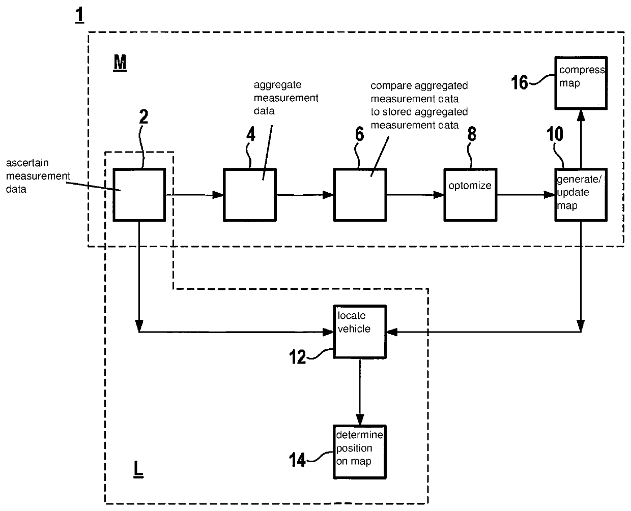
[0033]In a first step 2 of the method 1 according to the present invention, measurement data of the surroundings of the at least one vehicle are ascertained by at least one radar sensor. The at least one radar sensor may be situated in or on the at least one vehicle. The at least one radar sensor may generate radar waves continuously or at defined time intervals and receive radar waves reflected by objects and the vehicle's surroundings based on a time-of-flight analysis. For this purpose, the radar sensor has an electronic controller and an evaluation unit for controlling the generation of radar waves and for evaluating reflected radar waves. The reflected radar waves received by the radar sensor are ascertained in the form of measurement data or measurement points and are stored at least temporarily.

[0034]In a further step, the measurement data are aggregated 4. This serves in particular to reduce a measurement data density of the ascertained measurement data and to reduce a stora...


PUM


Abstract

A method and a system for mapping a surroundings of at least one vehicle and for locating the at least one vehicle. Measurement data of the vehicle's surroundings are ascertained by at least one radar sensor of the at least one vehicle, the measurement data of the at least one radar sensor being aggregated. The aggregated measurement data are compared with already existing aggregated measurement data. The aggregated measurement data are optimized by reducing measurement errors based on the comparison between the aggregated measurement data and the already existing aggregated measurement data. A map is generated or updated on the basis of the optimized aggregated measurement data, and the at least one vehicle being located on the generated or updated map by comparing the ascertained measurement data with the generated map.

Description

FIELD[0001]The present invention relates to a method for mapping a surroundings of at least one vehicle and for locating the at least one vehicle as well as to a system for implementing such a method.BACKGROUND INFORMATION[0002]Current autonomous or partially autonomous vehicles are highly dependent on provided cartographic information. The cartographic information is used for planning routes and for ascertaining the position of the vehicles. The cartographic information or maps are normally available at different levels. A first level is used for example for planning a precise lane course and driving maneuvers. On the basis of these data, autonomous or partially autonomous vehicles are able to keep to a lane or adapt. Another level has detectable objects, which are detectable by sensors in the vehicle and identifiable by a comparison with the existing information of the information level. On the basis of the identified objects, the vehicles are able to ascertain their relative posi...

Claims


Application Information

Patent Timeline
Patent Type & Authority Patents(United States)
IPC IPC(8): G01S13/89G01S7/41G01S13/931B60W60/00
CPCG01S13/89G01S7/41G01S13/931B60W60/001
Inventor PASSMANN, CHRISTIANZAUM, DANIELABELING, PETER CHRISTIAN
Owner ROBERT BOSCH GMBH
Why Eureka
Try Eureka