
Overscan for 3D display

Active Publication Date: 2022-11-08
ULTRA D COOPERATIEF U A
View PDF23 Cites 0 Cited by
  • Summary
  • Abstract
  • Description
  • Claims
  • Application Information

AI Technical Summary

Benefits of technology

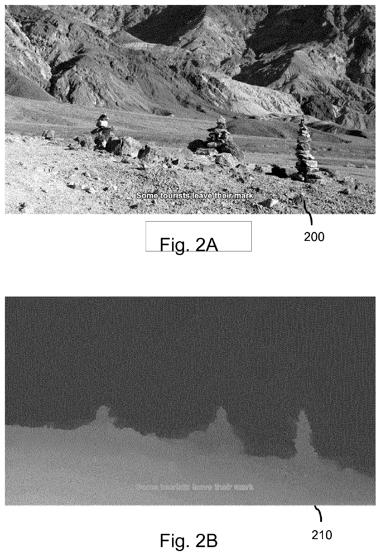
The inventors found that using overscan in 3D image data can cause low-frequency aliasing due to the slow variation in the phase used for interpolation. This can result in degraded display quality for relatively flat content. However, the invention recognizes that this issue can be minimized by adding depth information to the content.

Problems solved by technology

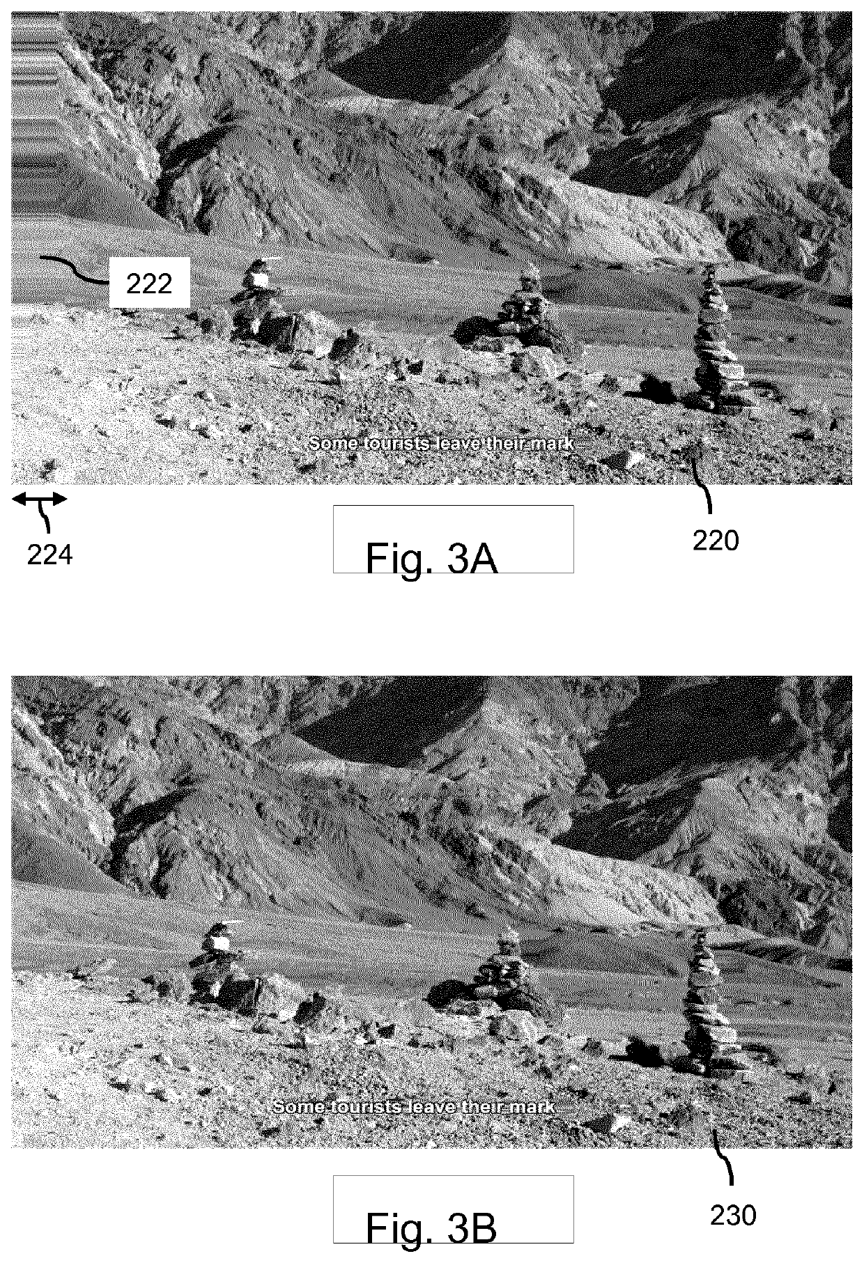
The inventors have recognized that a drawback of applying overscan to 3D image data is that the stretching may lead to a scale factor slightly above 1.0 which is to be applied to the image data, which may lead to (very) low-frequent aliasing caused by the slow variation in the phase used for the interpolation of the image data.
This has been found not to be greatly disturbing when the 3D content contains significant depth, since the variation in parallax disturbs and thereby reduces the visibility of this very low-frequent pattern.
However, when content is relatively flat, e.g., contains little depth information, the display quality of the content may be degraded as there may be no or too little parallax variation which may otherwise reduce the visibility of the aliasing.
Another drawback is that the degree of overscan may have to be selected to be relatively large to handle a scene containing a significant amount of depth, e.g., to avoid having to extrapolate content in such a worst-case situation.

Method used


Image

  • Overscan for 3D display
  • Overscan for 3D display
  • Overscan for 3D display

Examples


Embodiment Construction

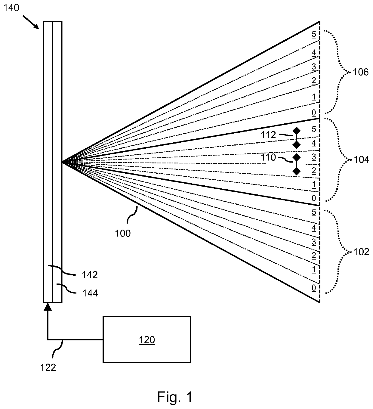
[0061]FIG. 1 shows a display processor 120 which is connected to a 3D display 140 and configured for providing a series of images, e.g., in the form of display data 122, to the 3D display. The 3D display 140 is an autostereoscopic 3D display for enabling stereoscopic viewing of content displayed thereon without a need for the user to wear glasses. The 3D display 140 comprises a light generating portion 142 which is typically comprised of an array of light emitting or light modulating elements. For example, the light generating portion 142 may be formed by a Liquid Crystal Display (LCD) panel and a backlight, as is known from the technical field of displays.

[0062]The 3D display 140 further comprises optical means 144 for redirecting light generated by the light generating portion 142 into different directions. The light generating portion 142 may be suitably arranged and cooperative with the optical means 144 such that a series of views 0-5 are emitted from the 3D display 140 in the ...


PUM


Abstract

A display processor and computer-implemented method are provided for processing three-dimensional [3D] image data for display on a 3D display. The 3D display is arranged for emitting a series of views of the 3D image data which enables stereoscopic viewing of the 3D image data at multiple viewing positions. The series of views may be displayed on the 3D display using overscan. The degree of overscan may be determined as a function of one or more depth range parameters, the one or more depth range parameters characterizing, at least in part, a degree of depth perceived by a viewer when the series of views is displayed on the 3D display.

Description

[0001]This application is the U.S. national phase of International Application No. PCT / EP2019 / 051617 filed Jan. 23, 2019 which designated the U.S. and claims priority to European Application No. 18157068.0 filed Feb. 16, 2018, the entire contents of each of which are hereby incorporated by reference.FIELD OF THE INVENTION[0002]The invention relates to a display processor and a computer-implemented method for processing three-dimensional [3D] image data for display on a 3D display. The invention further relates to a 3D display comprising the display processor, and to a computer readable medium comprising transitory or non-transitory data representing instructions arranged to cause a processor system to perform the method.BACKGROUND ART[0003]Increasingly, display devices such as televisions, digital photo frames, tablets and smartphones comprise 3D displays to provide a user with a perception of depth when viewing content on such a device. For that purpose, such 3D display devices may...

Claims


Application Information

Patent Timeline
Patent Type & Authority Patents(United States)
IPC IPC(8): H04N13/305H04N13/128H04N13/122H04N13/111
CPCH04N13/305H04N13/111H04N13/122H04N13/128H04N13/302
Inventor BARENBRUG, BART GERARD BERNARDROELEN, PETER
Owner ULTRA D COOPERATIEF U A
Learn More