Network for forming multiple beams from a planar array
a beamforming network and beam technology, applied in the direction of antennas, modular arrays, electrical equipment, etc., can solve the problems of limited conventional techniques for addressing this issue, impracticality for many applications, and inability to meet the requirements of many applications
- Summary
- Abstract
- Description
- Claims
- Application Information
AI Technical Summary
Benefits of technology
Problems solved by technology
Method used
Image
Examples
first embodiment
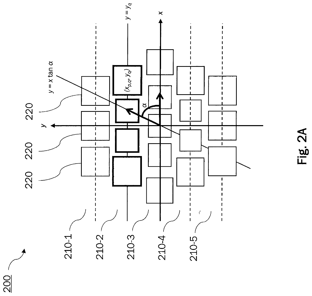
[0046]A generic planar array antenna (AA) for use by the embodiments of the disclosure is composed of a set of N radiating elements (REs) placed in the positions rn (disposed on the x-y plane) and excited by complex weights w(n). An example of the array geometry is schematically illustrated in FIG. 2A. The array antenna 200 in the example comprises a plurality of antenna elements (radiating elements, or elements for short) 200 that are arranged in a planar array of linear sub-arrays 210-1, . . . , 210-5. The linear sub-arrays 210 are arranged in parallel to each other and are assumed to extend in parallel to the x axis in the example.
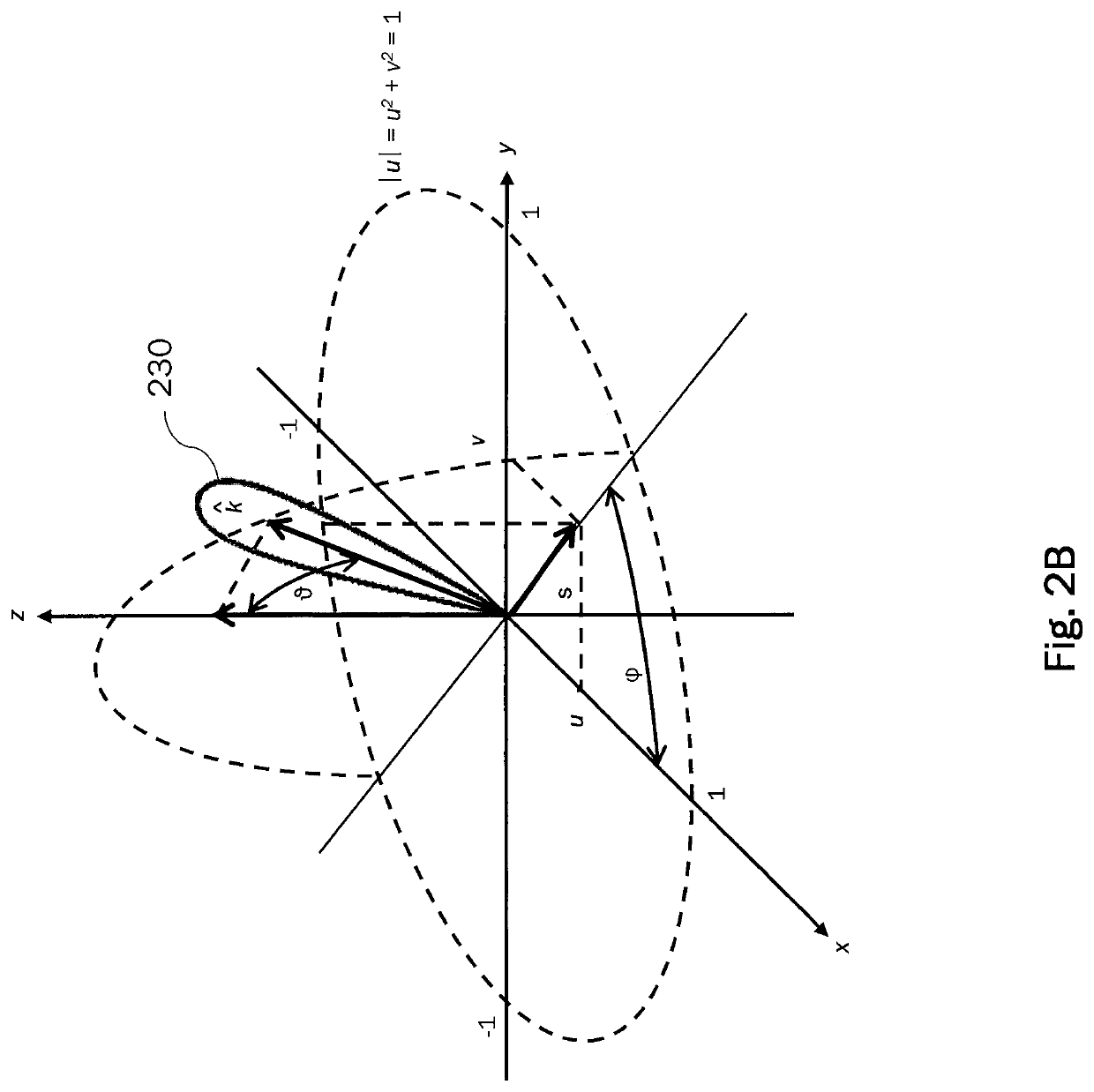
[0047]The array factor AF(u, v) can be evaluated by means of a Fourier transform of the array discrete field p(r) via
p(r)=Σn=1Nw(n)δ(r−rn) (1)
AF(u,v)=Σn=1Nw(n)exp(jk0{circumflex over (k)}·rn) (2)
where δ(r) is the Dirac delta function and
[0048]r=x^x+y^y(3)rn=x^xn+y^yn(4)k0=2πλ(5)
{circumflex over (k)}={circumflex over (x)}u+ŷv+{circumflex over (z)}...
second embodiment
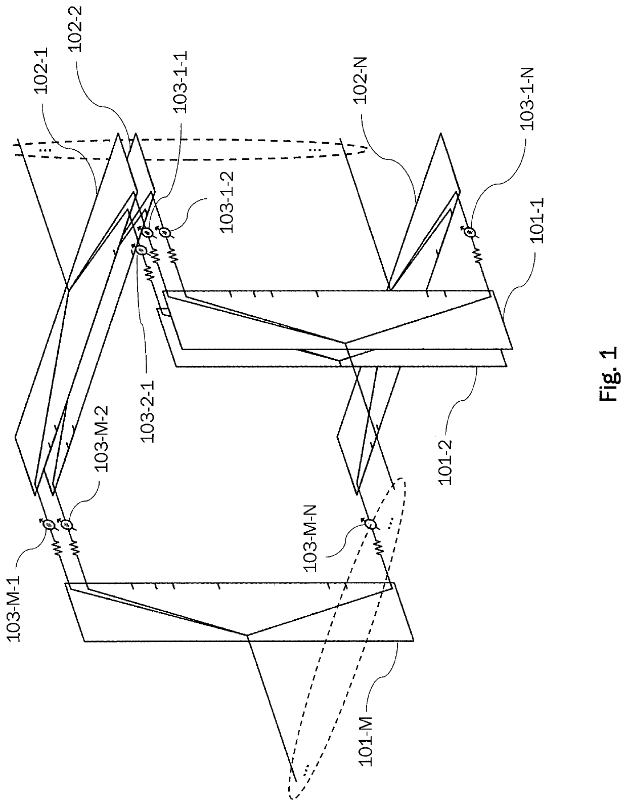
[0094]In another embodiment of the disclosure, a more general beam forming decomposition can be introduced that allows one to obtain for each beam a desired beam steering and a desired spatial beam dimension. Only differences with respect to the first embodiment will be described. The array antenna may be the same or of the same type as in the first embodiment.
[0095]In this embodiment, the linear sub-arrays are individually interconnected to a first set of beamforming matrices collimated to generate a first set of M1 fan beams along the direction cosines coordinates u=um1, where the fan beams have a beam-width proportional to Δum1 along the u axis.
[0096]In this embodiment, the transmission coefficient between the beam port m1 and the element ports p of the q-th beamforming sub-network (beamforming matrix) 10-q in the first set of beamforming sub-networks is generically indicated by tp,q|m1,q(1).
[0097]Assuming (without intended limitation) that each q-th sub-array is linear and align...
PUM
 Abstract
Description
Claims
Application Information
 - R&D
- Intellectual Property
- Life Sciences
- Materials
- Tech Scout
- Unparalleled Data Quality
- Higher Quality Content
- 60% Fewer Hallucinations
Browse by: Latest US Patents, China's latest patents, Technical Efficacy Thesaurus, Application Domain, Technology Topic, Popular Technical Reports.
© 2025 PatSnap. All rights reserved.Legal|Privacy policy|Modern Slavery Act Transparency Statement|Sitemap|About US| Contact US: help@patsnap.com


