Method and arrangement for condition monitoring of a rope of a hoisting apparatus

a hoisting apparatus and condition monitoring technology, which is applied in the direction of wing accessories, lifters, instruments, etc., can solve the problems of small variations of the electrical resistance of common tensile elements such as steel cords, unable to visually inspect internal tensile elements, and unable to meet the requirements of non-visual inspection

Active Publication Date: 2022-11-22
KONE CORP
View PDF9 Cites 0 Cited by
  • Summary
  • Abstract
  • Description
  • Claims
  • Application Information

AI Technical Summary

Benefits of technology

[0013]It is brought forward a new method for condition monitoring of a rope of a hoisting apparatus, which rope comprises one or more conductive load bearing members for bearing the load exerted on the rope in longitudinal direction and extending parallel to each other and to the longitudinal direction of the rope, in which method an alternating magnetic field is generated by an at least one eddy current testing probe placed near said rope, said alternating magnetic field causing eddy currents in said rope, a secondary magnetic field generated by said eddy currents is detected in said rope by said at least one eddy current testing probe as eddy current detection data, and said eddy current detection data is utilized for on-line monitoring of said rope. Hereby, one or more of the above-mentioned advantages and / or objectives are achieved. These advantages and / or objectives are further facilitated with the additional preferred features and / or steps described in the following.
[0014]In a preferred embodiment of said method, said eddy current detection data is used for determining of the condition, the position, the alignment or the tension of said moving rope.
[0015]In a preferred embodiment of said method, information about the location of a fault and / or damage in the rope is provided and / or one or more parameters for determining the type of a fault and / or damage in the rope is provided.

Problems solved by technology

The visual inspection of the internal tensile elements is generally regarded as impossible and hence the need arises for non-visual inspection.
There are some drawbacks to this method.
It has been found, however, that non negligible damages may nevertheless result in small variations of the electrical resistance of common tensile elements such as steel cords.
Consequently, the sensitivity of the resistance-based inspection is not satisfactory.
If damage occurs to an extent great enough to break the conductive member, the electrical circuit is broken.
There are some drawbacks to this method.
Furthermore, the method provides no information on the location of the damage along the length of the rope.
In addition to a damage or defect in the rope, slackness and misalignment of the rope might cause serious problems in use of the hoisting apparatus.
A drawback of the known elevators has been that moving of a rope in the axial direction outside its intended course, and further development of the problem into even more hazardous state have not been prevented in an adequately reliable manner.
This has been difficult especially with elevators where said mechanical shape-locking between the drive wheel and the rope engaging the drive wheel has been inadequately reliable or unavailable for some reason such as due to preference to utilize cambered shape of the drive wheel for rope position control.

Method used


Image

  • Method and arrangement for condition monitoring of a rope of a hoisting apparatus
  • Method and arrangement for condition monitoring of a rope of a hoisting apparatus
  • Method and arrangement for condition monitoring of a rope of a hoisting apparatus

Examples


Embodiment Construction

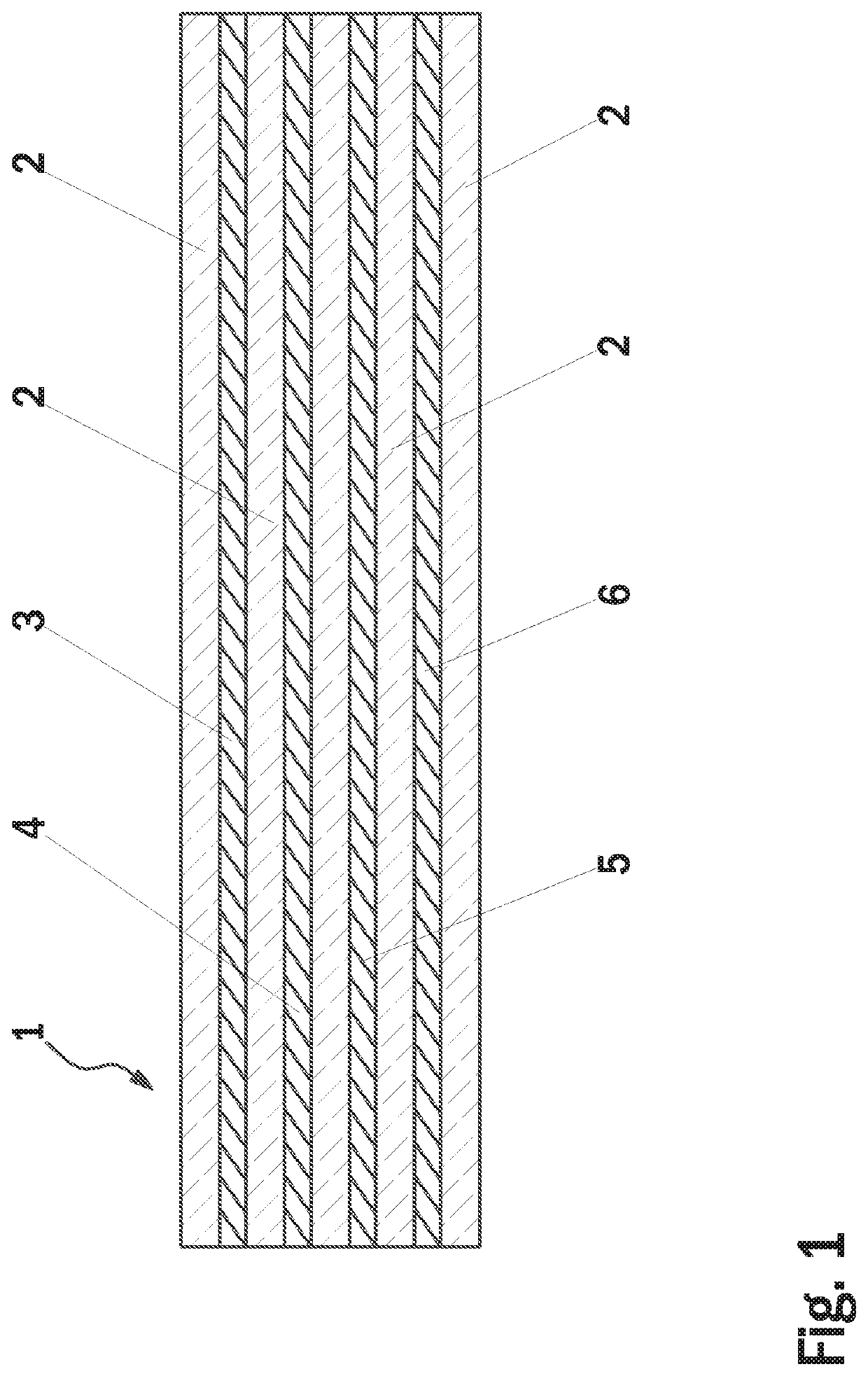
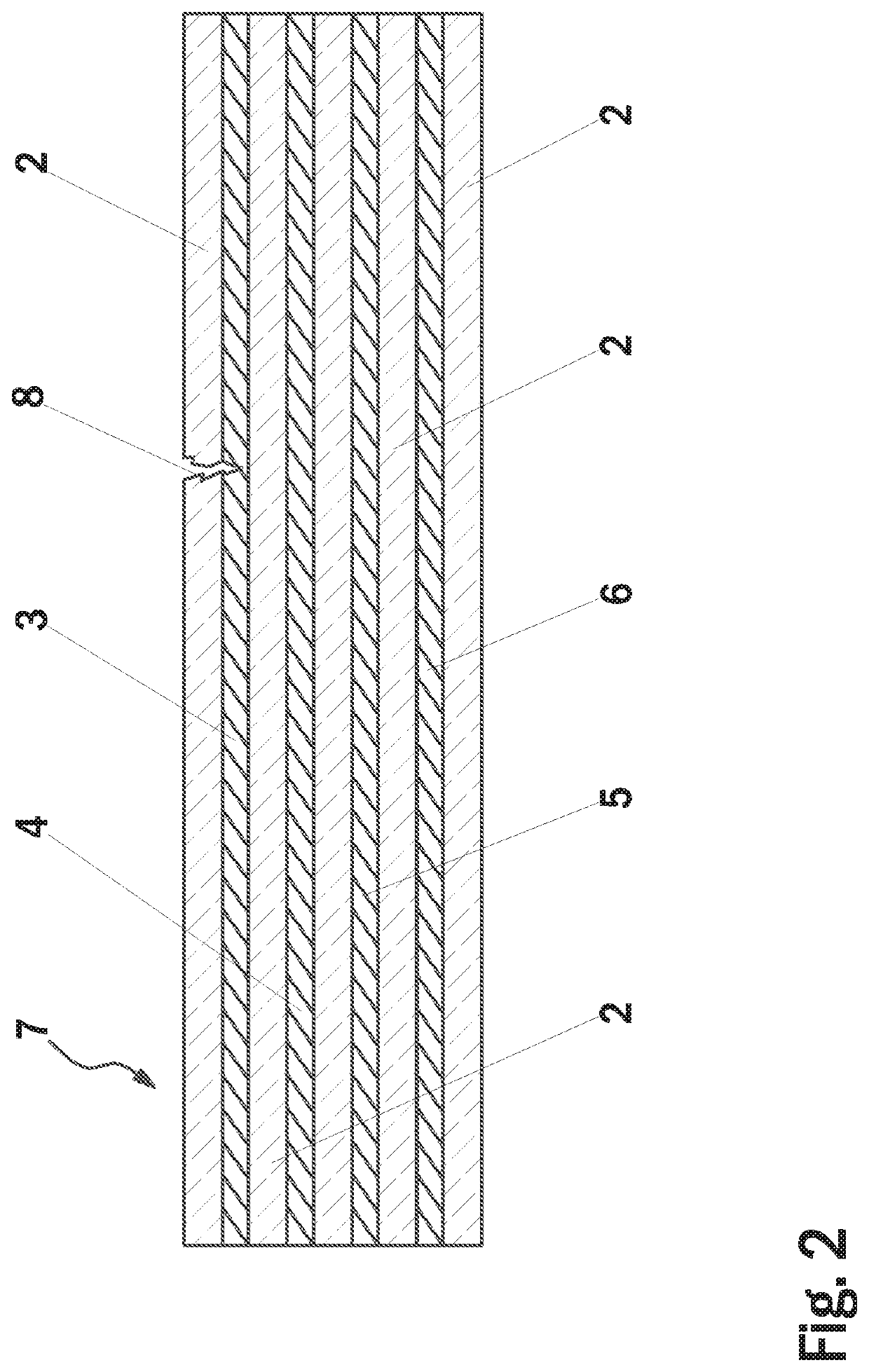
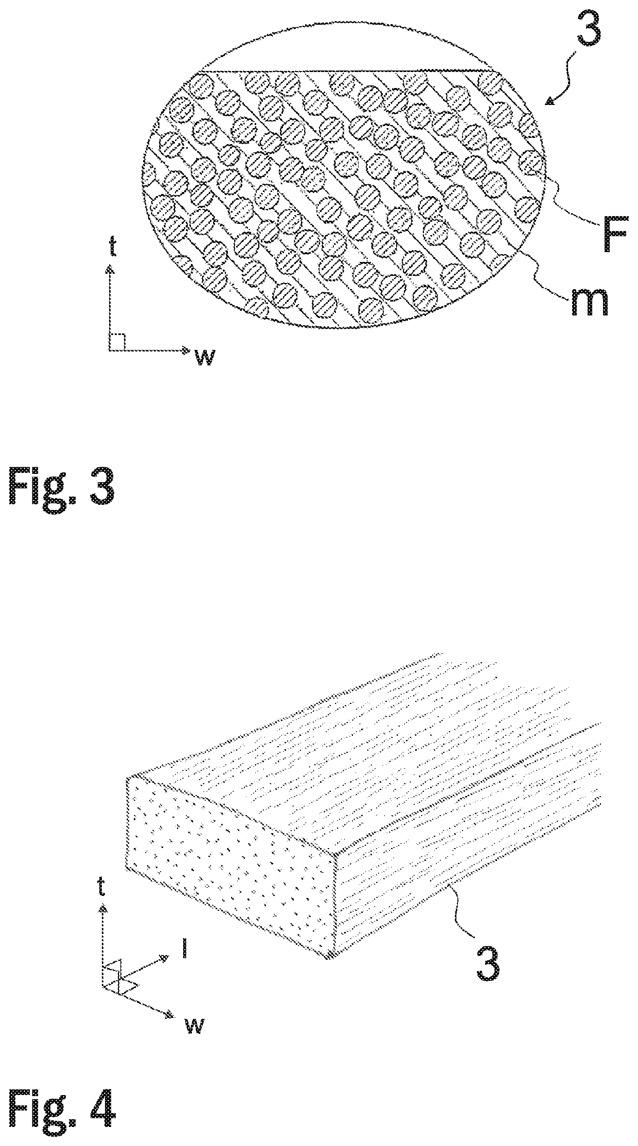
[0055]FIG. 1 illustrates a rope of a hoisting apparatus according to one embodiment of the present invention. In the presented embodiment, the hoisting rope 1 is belt-shaped, i.e. larger in width direction than thickness direction. The hoisting rope 1 comprises a non-conductive coating 2, and a plurality of conductive load bearing members 3-6 for bearing the load exerted on the hoisting rope 1 in longitudinal direction thereof, which are adjacent in width direction of the hoisting rope 1. The load bearing members 3-6 are embedded in the non-conductive coating 2 and extend parallel to each other as well as to the longitudinal direction of the hoisting rope 1 unbroken throughout the length of the hoisting rope 1. The coating 2 forms the surface of the hoisting rope 1 and extends between adjacent load bearing members 3-6, thereby isolating them from each other both mechanically and electrically. The said conductive load bearing members 3-6 may be made of non-metal material. The said co...


PUM

PropertyMeasurementUnit
distanceaaaaaaaaaa
speedaaaaaaaaaa
magnetic fieldaaaaaaaaaa

Abstract

The invention relates to a method for condition monitoring of a rope of a hoisting apparatus, and to an arrangement for condition monitoring of a rope of a hoisting apparatus, preferably of an elevator for transporting passengers and / or goods. The arrangement for condition monitoring of a rope of a hoisting apparatus according to the present invention, in which rope comprises one or more conductive load bearing member for bearing the load exerted on the rope in longitudinal direction and extending parallel to each other and to the longitudinal direction of the rope, comprises an at least one eddy current testing probe, placed near said rope for generating an alternating magnetic field, said alternating magnetic field causing eddy currents in said rope, and for detecting a secondary magnetic field being generated by said eddy currents in said rope as eddy current detection data, and an on-line monitoring unit receiving and utilizing said eddy current detection data for on-line condition monitoring of said rope.

Description

[0001]This application claims priority to European Patent Application No. EP17211045.4 filed on Dec. 29, 2017, the entire contents of which are incorporated herein by reference.FIELD OF THE INVENTION[0002]The invention relates to a method for condition monitoring of a rope of a hoisting apparatus, and to an arrangement for condition monitoring of a rope of a hoisting apparatus. Said hoisting apparatus is preferably an elevator for transporting passengers and / or goods.BACKGROUND OF THE INVENTION[0003]An elevator typically comprises an elevator car and a counterweight, which are vertically movable in a hoistway. These elevator units are interconnected to each other by a hoisting roping. The hoisting roping is normally arranged to suspend the elevator units on opposite sides of a drive wheel. For providing force for moving the suspension roping, and thereby also for the elevator units, the elevator comprises a motor for rotating the drive wheel engaging the hoisting roping. The motor i...

Claims


Application Information

Patent Timeline
Patent Type & Authority Patents(United States)
IPC IPC(8): B66B7/12B66B1/34B66B7/06G01L5/10G01N27/9013B66B1/46B66B1/24G01N27/904
CPCB66B7/1223B66B1/3484B66B7/062B66B7/123G01L5/10G01N27/902G01N27/9026B66B1/2458B66B1/468E05Y2400/54E05Y2400/664E05Y2900/104G01N27/904
Inventor JUNTUNEN, MIKAPURANEN, MIKKOANTIN, KIMSANTOS, TELMOMACHADO, MIGUEL
Owner KONE CORP
Why Eureka
Try Eureka