Automatic multi-stage fabric generation for FPGAs

a fabric generation and multi-stage technology, applied in the direction of transmission, electrical equipment, etc., can solve the problems of increasing power consumption, increasing the latency of signals affecting the maximum clock speed of operation, and inefficient interconnection networks in integrated circuits, etc., to achieve low cross points, reduce power consumption, and reduce the effect of power consumption

Active Publication Date: 2022-11-22
KONDA TECH
View PDF13 Cites 0 Cited by
  • Summary
  • Abstract
  • Description
  • Claims
  • Application Information

AI Technical Summary

Benefits of technology

[0015]Fabric disclosed provide high routability for broadcast, unicast and multicast connections, yet with the benefits of significantly lower cross points hence smaller area, lower signal latency, lower power and with significant fast scheduling or routing time. Various scheduling methods are also disclosed to schedule a set of multicast connections in the multi-stage pyramid network.

Problems solved by technology

However VLSI layouts, known in the prior art, of these interconnection networks in an integrated circuit are inefficient, not scalable and not replicable.
Due to the inefficient and in some cases impractical VLSI layout of Benes, Benes Pyramid, Butterfly fat tree networks, and Butterfly fat pyramid networks on a semiconductor chip, today mesh networks and segmented mesh networks are widely used in the practical applications such as field programmable gate arrays (FPGAs), programmable logic devices (PLDs), and parallel computing interconnects.
The prior art VLSI layouts of Benes, Benes Pyramid, Butterfly fat tree networks, Pyramid networks and VLSI layouts of mesh networks and segmented mesh networks require large area to implement the switches on the chip, large number of wires, longer wires, with increased power consumption, increased latency of the signals which effect the maximum clock speed of operation.
Some networks may not even be implemented practically on a chip due to the lack of efficient layouts.

Method used


Image

  • Automatic multi-stage fabric generation for FPGAs
  • Automatic multi-stage fabric generation for FPGAs
  • Automatic multi-stage fabric generation for FPGAs

Examples


Embodiment Construction

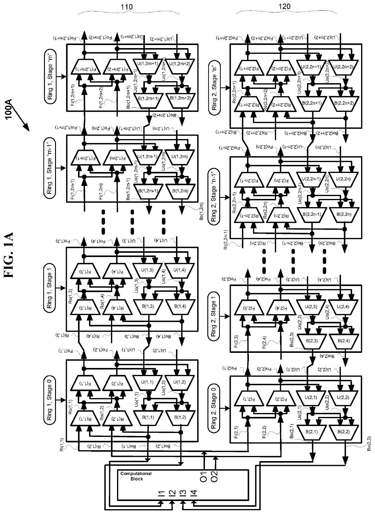
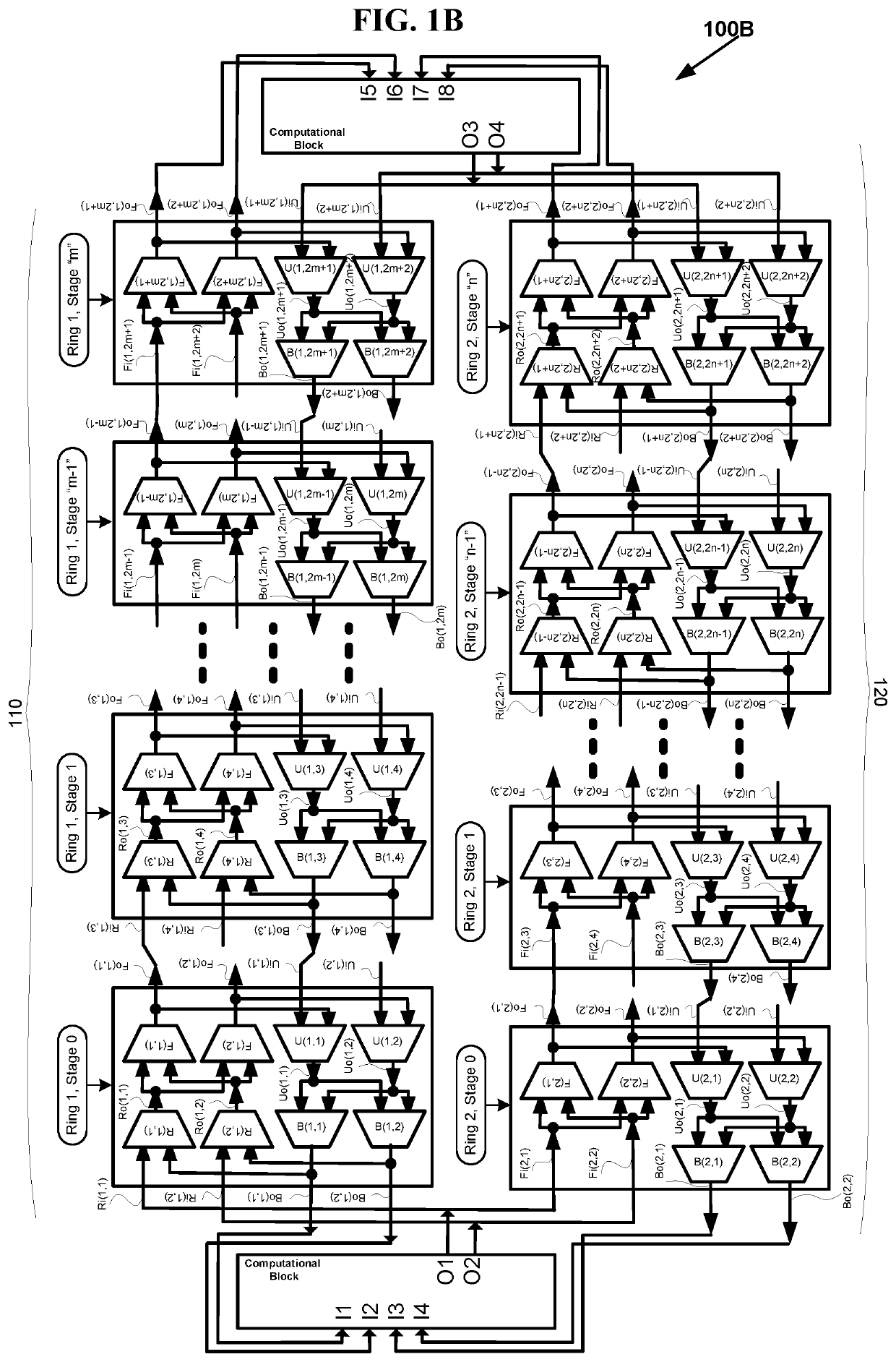
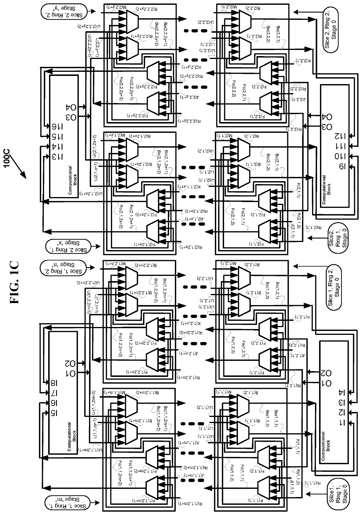
[0074]Fully connected multi-stage pyramid networks are an over kill in every dimension such as area, power, and performance for certain practical routing applications and need to be optimized to significantly improve savings in area, power and performance of the routing network. The present invention discloses several embodiments of the optimized multi-stage pyramid networks for practical routing applications along with their VLSI layout (floor plan) feasibility and simplicity.

[0075]The multi-stage pyramid networks considered for optimization in the current invention include: generalized multi-stage networks V(N1,N2,d,s), generalized folded multi-stage networks Vfold(N1,N2,d,s), generalized butterfly fat tree networks Vbft(N1,N2,d,s), generalized multi-link multi-stage networks Vmlink(N1,N2,d,s), generalized folded multi-link multi-stage networks Vfold-mlink(N1,N2,d,s), generalized multi-link butterfly fat tree networks Vmlink-bft (N1,N2,d,s), generalized hypercube networks Vhcube(N...


PUM


Abstract

Systems and methods to automatically or manually generate various multi-stage pyramid network based fabrics, either partially connected or fully connected, are disclosed by changing different parameters of multi-stage pyramid network including such as number of slices, number of rings, number of stages, number of switches, number of multiplexers, the size of the multiplexers in any switch, connections between stages of rings either between the same numbered stages (same level stages) or different numbered stages, single or multi-drop hop wires, hop wires of different hop lengths, hop wires outgoing to different directions, hop wires incoming from different directions, number of hop wires based on the number and type of inlet and outlet links of large scale sub-integrated circuit blocks. One or more parameters are changed in each iteration so that optimized fabrics are generated, at the end of iterations, to route a given set of benchmarks or designs having a specific connection requirements.

Description

CROSS REFERENCE TO RELATED APPLICATIONS[0001]This application is Continuation Application to and claims priority of U.S. application Ser. No. 16 / 671,193 entitled “AUTOMATIC MULTI-STAGE FABRIC GENERATION FOR FPGAs” by Venkat Konda assigned to the same assignee as the current application, filed Nov. 1, 2019, which is Continuation Application to and claims priority of U.S. application Ser. No. 15 / 859,726 entitled “AUTOMATIC MULTI-STAGE FABRIC GENERATION FOR FPGAs” by Venkat Konda assigned to the same assignee as the current application, filed Jan. 1, 2018, which is Continuation In Part Application to and claims priority of U.S. application Ser. No. 14 / 329,876 entitled “FAST SCHEDULING AND OPTIMIZATION OF MULTI-STAGE HIERARCHICAL NETWORKS” by Venkat Konda assigned to the same assignee as the current application, filed Jul. 11, 2014, issued as U.S. Pat. No. 9,509,634 on Nov. 29, 2016, which claims priority of U.S. Provisional Patent Application Ser. No. 61 / 846,083 entitled “FAST SCHEDULI...

Claims


Application Information

Patent Timeline
Patent Type & Authority Patents(United States)
IPC IPC(8): H04L49/15H04L49/102H04L49/101H04L49/1515
CPCH04L49/15H04L49/101H04L49/102H04L49/1515
Inventor KONDA, VENKAT
Owner KONDA TECH
Why Eureka
Try Eureka