Self locking bi-directional lock/release fixture

a self-locking, bi-directional technology, applied in the direction of machine supports, washstands, other domestic objects, etc., can solve the problems of no teaching or suggestion in lan of any form of self-locking and/or unlocking by turning, adverse conditions of side load on a held object, plastic part breakage, etc., to increase the load resistance of my invention and small structure

Inactive Publication Date: 2001-05-03
TRACY DAVID S
View PDF0 Cites 46 Cited by
  • Summary
  • Abstract
  • Description
  • Claims
  • Application Information

AI Technical Summary

Benefits of technology

34. As larger pull loads were applied, such loads would deform and deflect the bottoms of the keeper pairs upward, and the mating edge of the puck downward, creating unintended sloping surfaces. These large load tests of direct pull on the latched object, combined with the above-noted deflected surfaces overcome the overlapped spring tension and force the striker keeper pairs open. Upon application of sufficient force the keepers withdrew into the casing and resulted in a premature release. A mating notch and ridge interlocks the keeper strikers and the casing openings, and that interlock solved the premature release problem.
35. Keeper interlocks on the strikers and casing openings--one per keeper pair--take the form of mating recess and keeper ridges which become mutually engaged during a direct pull. Thus, a pair of raised ridges or teeth on the upper surface of a keeper pair engages with a matching mating recess in the underside of the top casing opening that houses the keeper pair. These interlocks serve an anti-spread function that prevent the keepers from spreading apart and / or retracting under high direct pull loads. Such spreading otherwise results in an undesired release. This refinement, though seemingly small in structure, has increased the load resistance of my invention several fold, and makes it a secure lock under dynamic load conditions.

Problems solved by technology

In particular, there is no teaching or suggestion in Lan of any form of self locking and / or unlocking by turning, much less any split striker latching operation for a bi-direction rotational release.
As research continued on my invention--and destructive tests on pre-production models were done--some plastic part breakage was experienced under extreme loads.
I discovered that a side load on a held object was an adverse condition.
Such a load (depending on the height of the object experiencing the load) caused a large moment arm force which might result in part breakage.
However, this correction--as more and more tests were done--revealed another problem relating to direct pulls on a latched object.
As larger pull loads were applied, such loads would deform and deflect the bottoms of the keeper pairs upward, and the mating edge of the puck downward, creating unintended sloping surfaces.
Upon application of sufficient force the keepers withdrew into the casing and resulted in a premature release.
Such spreading otherwise results in an undesired release.

Method used


Image

  • Self locking bi-directional lock/release fixture
  • Self locking bi-directional lock/release fixture
  • Self locking bi-directional lock/release fixture

Examples


Embodiment Construction

)

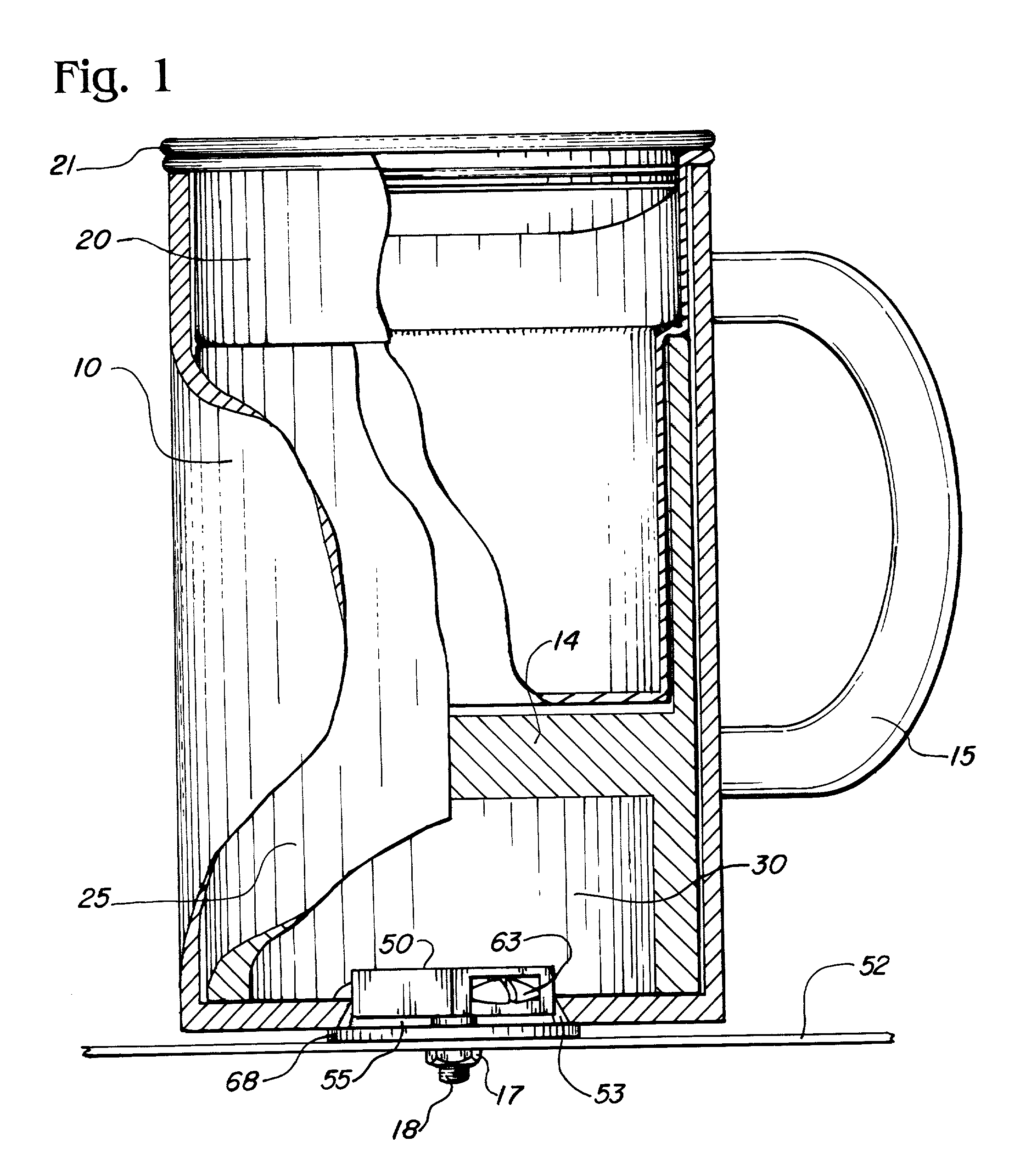
63. Turning now to FIG. 1, a cutaway sectional view depicts an outer container 10 having a handle 15, shown schematically, a removable mug 20, lid 21 and adapter insert 25. This container 10 may be made of any suitable material and may, or may not, be insulated as desired. Located within the container 10 is an adapter insert 25 that is normally seated against the bottom of container 10 in one of two possible directions. Mug 20 fits within insert 25 as shown.

64. Insert 25 is a double open-ended cylinder having two separate different diameter recesses of varying depth between the open end and a dividing partition 14 separating the cylinders. The diameters, depth and wall thickness of adapter 25 are chosen such that insert 25 can accommodate different-sized cups, cans or bottles within the outer container 10. FIG. 6 shows the adapter insert 25 as being capable of holding either a can 8 or a bottle 9.

65. Insert 25 is placed in container 10 in either one or the other of a pair of invert...


PUM


Abstract

Invention provides a self latching, object-holding fixture designed to release a held object whenever the object is turned slightly in either direction. Fixture has a shaped housing and the object to be held has a mated opening of a similar matching shape. Placing an object to be held locks the object to the fixture by spring-loaded latching action. The fixture housing covers a fixed spring holding base that is anchored by any suitable means to a support surface. Covering that fixed-position base, except for exposed spring-loaded keeper latches, is a rotatable casing having a pair of spring compression cam surfaces carried by the casing. Using a cam follower action, these cam surfaces selectively cause the spring to collapse in response to the rotation of the casing holding in either direction of casing rotation. As the object/casing is turned slightly, this cam follower/spring collapse action releasably disengages the keepers from the object being held.

Description

1. This continuation-in-part application is from my presently pending parent application of the same title filed on Jan. 5, 1996 having Ser. No. 08 / 583,275.2. The field of the invention relates to a new and improved lock / release method and a self-locking / bi-directional, turn-release fixture. More specifically, the field relates to a bi-directional striker actuated release for such a locking fixture, and particularly to such a fixture that will release a locked device by a slight turn applied to the locked device in either a clockwise or counter clockwise direction.3. The specific field of the invention as described herein relates to an environment of travel containers for a vehicle, but other environments such as spice racks, shipboard use holders, toys and the general latch / release field will equally benefit from the principles of this novel inventionDESCRIPTION OF PRIOR ART4. In today's society, our fast paced and hectic travel requirements, have made drinking coffee and other liq...

Claims


Application Information

Patent Timeline
Patent Type & Authority Applications(United States)
IPC IPC(8): B60N3/10E05C19/06
CPCB60N3/10E05C19/06
Inventor TRACY, DAVID S.
Owner TRACY DAVID S
Why Eureka
Try Eureka