
Wet type buffing method, deposition plating method, work buffing method, work buffing apparatus, barrel buffing apparatus, work surface treating method, work supporting unit for barrel buffing apparatus, and buffing medium

a barrel buffing and buffing technology, applied in the direction of flexible parts wheels, manufacturing tools, edge grinding machines, etc., can solve the problems of difficult to improve the buffing efficiency of the conventional buffing method, the oxide film or the like can be removed from the surface of the work only with much difficulty, and the inconvenience inherent in the wet type buffing operation, so as to eliminate the inconvenience inherent, smooth buffing

Inactive Publication Date: 2001-06-14
KAWASAKI SHUJI +2
View PDF0 Cites 7 Cited by
  • Summary
  • Abstract
  • Description
  • Claims
  • Application Information

AI Technical Summary

Benefits of technology

[0021] The present invention has been made in order to eliminate the inconvenience inherent to the first conventional technique as mentioned above. Therefore, a first object of the present invention is to provide a wet type buffing method which assures that an operational efficiency of each wet type buffing operation can be improved via a series of buffing steps, and consequently, each work can smoothly be buffed (hereinafter referred to as "a first invention").
[0022] In addition, the present invention has been made in order to eliminate the inconvenience inherent to the second conventional technique as mentioned above. Therefore, a second object of the present invention is to provide a deposition plating method which assures that the thickness of a deposition plated layer can be reduced in excess of the thickness obtained by the conventional deposition plating method, each deposition plating process can quickly be practiced, and consequently, an operational efficiency of each deposition plating operation can be improved for each buffed work in association with the quick execution of the buffing process (hereinafter referred to as "a second invention").
[0023] Additionally, the present invention has been made in order to eliminate the inconvenience inherent to the third conventional technique as mentioned above. Therefore, a third object of the present invention is to provide a work buffing method which assures that dirty foreign matters adhering to the surface of a work to be buffed and an oxide film extending over the surface of the work can easily be removed, thereafter, the surface of the work to be buffed is subjected to dry buffing, and subsequently, the surface of the work can be subjected to dry buffing (hereinafter referred to as "a third invention").

Problems solved by technology

However, with respect to the conventional buffing method as mentioned above, in the case that a buffing agent having acidity is used like the first-mentioned conventional buffing method, the buffing efficiency can be improved but there appears an inconvenience that it is appreciably difficult to smoothly buff each work.
On the other hand, in the case that a buffing agent having alkality is used like the last-mentioned conventional buffing method, each work can smoothly be buffed but an oxide film or the like remaining on the surface of the work can be removed from the work only with much difficulties.
As a result, there appears an inconvenience that it is difficult to improve the buffing efficiency with the conventional buffing method.
However, with respect to the first-mentioned conventional buffing method, since dry type buffing is employed as buffing means, the buffing time can be shortened but the resultant buffed surface of the work exhibits poor surface roughness with a reduced degree of brightness.
Consequently, there arises an inconvenience that the thickness of a deposition plated layer should be increased, and moreover, it is practically difficult to improve the operational efficiency of each deposition plating operation performed for the work.
As a result, the thickness of deposition plating can be reduced but the time required for performing each buffing operation is undesirably elongated.
For this reason, an inconvenience arises in the same manner as mentioned above such that it is practically difficult to improve the operational efficiency attained by the deposition plating process with each buffed work.
However, when the conventional buffing method as mentioned above is employed for the purpose of buffing each work, this work is subjected merely to wet buffing in the presence of an acid detergent liquid.
For this reason, there arises an inconvenience that dirty foreign matters are removed from the surface of the work with some difficulty, and moreover, it is practically difficult to remove an oxide film from the surface of the work due to the substantially intense strengthening achieved for the work in the presence of the acid detergent liquid.
However, when the conventional buffing method as mentioned above is employed, the surface of the work to be buffed is oxidized during each buffing operation, causing an oxide film to be readily formed on the work.
As a result, there arises an inconvenience that it is practically difficult to improve a quality of each buffing operation.
Consequently, there arises an inconvenience that it is practically difficult to improve the operational efficiency attained by the buffing operation.
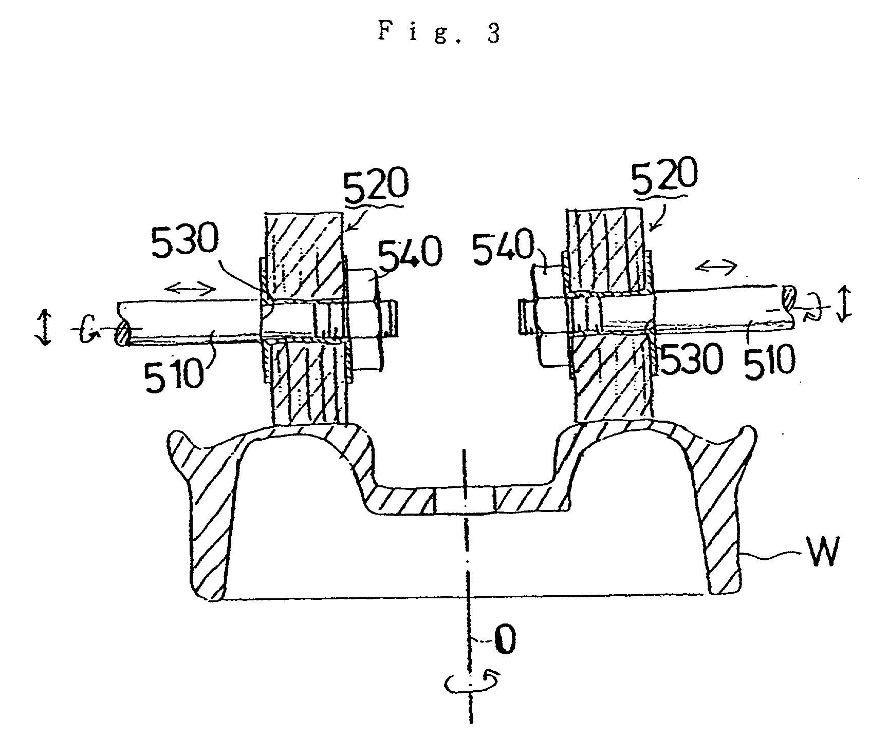
As a result, there arises an inconvenience that it is practically difficult to determine the position assumed by each buffing wheel 520 relative to the work W.
However, with the conventional barrel buffing apparatus constructed in the above-described manner, since an operational extent attained by the buffing medium is limited within a certain range by the buffing medium, it is required that the buffing medium is replaced with other one in dependence on an object of each buffing operation, i.e., a rough buffing step, an intermediate finish buffing step and a final finish buffing step, and alternatively, it is required that a plurality of barrel buffing apparatuses each including a buffing medium selected in such a manner as to match with a certain object of the conventional barrel buffing apparatus are preparatively arranged.
At any rate, there arises an inconvenience that it is practically difficult to improve an operational efficiency of each barrel buffing operation with the conventional barrel buffing apparatus.
However, with the foregoing conventional technique, each work is subjected to buffing merely by using operator's hands.
Consequently, there arises an inconvenience that an operational extent attained by each buffing operation readily fluctuates, resulting in each coating operation being unavoidably performed with some fluctuation.
In addition, since it is required that burrs formed on the work because of a necessity for correctly performing each coating operation are removed from the work, there arises an inconvenience that it is practically difficult to improve the operational efficiency attained by employing the foregoing conventional technique.
However, with the conventional barrel buffing apparatus, since each work is dipped in the barrel buffing medium received in the buffing medium receiving container while it is seized with the aid of a certain seizing instrument, there arises an inconvenience that it is difficult to hold the work in the immovably seized state.
In addition, there arises an convenience that it is difficult to attach the work to the seizing instrument and detach the work from the seizing instrument.
Especially, in the case of a work having a large mass, the last-mentioned inconvenience appears remarkably.

Method used


Image

  • Wet type buffing method, deposition plating method, work buffing method, work buffing apparatus, barrel buffing apparatus, work surface treating method, work supporting unit for barrel buffing apparatus, and buffing medium
  • Wet type buffing method, deposition plating method, work buffing method, work buffing apparatus, barrel buffing apparatus, work surface treating method, work supporting unit for barrel buffing apparatus, and buffing medium
  • Wet type buffing method, deposition plating method, work buffing method, work buffing apparatus, barrel buffing apparatus, work surface treating method, work supporting unit for barrel buffing apparatus, and buffing medium

Examples


embodiment of first invention

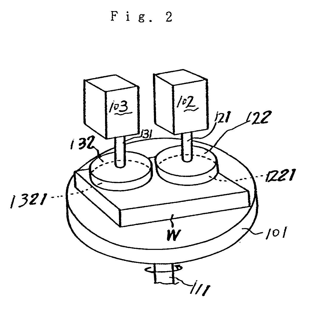
[0082] FIG. 1 shows an embodiment of a wet type buffing method to be practiced according to the present invention, and this buffing method is practiced by way of a series of wet type buffing steps.

[0083] A step A represents a rough buffing step, a step B represents a finish buffing step, and a step C represents a final finish buffing step.

[0084] These steps A, B and C will be described below with reference to FIG. 2. In the drawing, reference numeral 101 designates a supporting board, and reference numeral 111 designates a supporting shaft arranged along the axis line of the supporting board. The supporting board 101 is rotated about the supporting shaft 111 with the use of suitable means (not shown) in the direction identified by an arrow mark. Reference character W designates a plate-like work, and this plate-like work is placed on the upper surface of the supporting board 101. In the shown case, the work W serves as a surface to be buffed (hereinafter referred to as a buffing sur...

embodiment of second invention

[0088] This second invention will be described below with respect to an embodiment thereof on the assumption that an aluminum wheel is employed as a work.

[0089] Firstly, the aluminum wheel is heated in hot water at a temperature of about 80.degree. C., and then, it is subjected to dry buffing by employing the ordinary method. Thereafter, the aluminum wheel is subjected to wet buffing while maintaining the working state represented by a temperature of about 30.degree. C.

[0090] After the buffing operation is completed, the aluminum wheel is subjected to deposition plating by employing the ordinal deposition plating method. Any type of deposition plating such as chromium deposition plating, titanium deposition plating or the like may be employed for the aluminum wheel. It should be noted that the thickness of a film formed by the deposition plating generally remains within the range from about 0.1 .mu.m to 0.2 .mu.m. When the deposition plating is used in place of the conventional chro...

embodiment of third invention

[0091] For example, an aluminum wheel usable for a vehicle or the like can be noted as a work employable for carrying out this third invention. However, the third invention should not be limited only to the aluminum wheel as a work but all products each usable as a work are involved in the concept of the work in the third invention.

[0092] Usually, a wet type buffing method or a dry type buffing method for buffing the buffing surface of a work in the presence of a buffing agent is employed as a buffing method in the third invention. In this case, the number of buffs usable for carrying out the third invention may be limited only to one. Alternatively, a plurality of buffs may be used for carrying out the third invention. Incidentally, a buff wheel can be noted as one example which represents the buff.

[0093] To carry out the third embodiment, an ordinary wet type buffing method and an ordinary dry type buffing method can be employed for practicing the wet type buffing method and the d...


PUM

PropertyMeasurementUnit
Angleaaaaaaaaaa
Angleaaaaaaaaaa
Diameteraaaaaaaaaa

Abstract

A wet type buffing method is practiced such that a final buffing step is conducted in a buffing liquid having alkality and the remaining buffing steps are conducted in other buffing liquid having acidity. A work buffing apparatus is constructed such that a disconnection preventive member is disposed at the foremost end of a shaft for a work, the outside of a buffing wheel comes in contact with the disconnection preventive member, a tightening nut is threadably engaged with the buffing wheel, and the buffing wheel is tightly fixed to the shaft by displacing the tightening nut along the shaft. In addition, a surface treatment conducting method is practiced such that each surface treatment is conducted after a work is subjected to barrel buffing before or after the surface treatment. Additionally, a work supporting apparatus includes a buffing medium receiving container having a buffing medium received therein and a work supporting arm. Further, a buffing medium employable for a buffing apparatus is composed of grain of soft material or small block of the soft material.

Description

[0001] 1. Field of the Invention[0002] The present invention relates to a wet type buffing method, a deposition plating method, a work buffing method, a work buffing apparatus, a barrel buffing apparatus, a work surface treating method, a work supporting unit for a barrel buffing apparatus, and a buffing medium. Particularly, with respect to the deposition plating method, the present invention is applicable to a method of conducting deposition plating after a work is subjected to buffing, and moreover, with respect to the work buffing apparatus, the present invention is applicable to a method of mounting a buffing wheel on the work buffing apparatus.[0003] 2. Prior ArtFirst Conventional Technique and its Drawbacks[0004] The conventional wet type buffing method is exemplified by a method of improving a buffing efficiency by using an acid buffing agent and a method of smoothly buffing a work by using an alkaline buffing agent.[0005] However, with respect to the conventional buffing me...

Claims


Application Information

Patent Timeline
IPC IPC(8): B24B1/00B24B29/00B24B29/02B24B31/06B24B31/14B24B57/02B24D13/20
CPCB24B1/00B24B29/00B24B29/02B24B31/06B24B31/064B24B31/14B24B57/02B24D13/20
Inventor KAWASAKI, SHUJIMATSUSHITA, AKITAKA
Owner KAWASAKI SHUJI
Learn More