Heavy vehicle lifting device and method

a technology for lifting devices and heavy vehicles, applied in lifting devices, soil shifting machines/dredgers, lifting frames, etc., can solve the problems of inability to use the above method outside the workshop, significant accident risk, and take up to six days to lift and lower a large mechanical shovel. , to achieve the effect of easy transportation and increased lifting speed

Inactive Publication Date: 2001-06-21
3991814 CANADA
View PDF0 Cites 12 Cited by
  • Summary
  • Abstract
  • Description
  • Claims
  • Application Information

AI Technical Summary

Benefits of technology

[0007] It is also an aim of the present invention to provide a lifting device which is adapted to increase the speed of the lifting operation.
[0008] It is a further aim of the present invention to provide such a lifting device which is designed for offering ease of assembly and disassembly. It is a still further aim of the present invention to provide a shovel lifting device which is adapted for lifting different models of shovels.
[0009] It is a still further aim of the present invention to provide a shovel lifting device which is easy to transport.

Problems solved by technology

With this method, it takes up to six days for lifting and lowering a large mechanical shovel.
Moreover, the operators must work under the load during the lifting operation and there is thus a significant risk of accident, for instance, because this method does not provide a high degree of stability (e.g. the wood blocks can sometimes yield or at least be crushed under the high load being lifted).
Furthermore, the above method cannot be used outside of the workshop since it is not adapted to compensate for the packing soil effect which could occur at the lifting point during the lifting operation of such heavy mechanical shovels.

Method used


Image

  • Heavy vehicle lifting device and method
  • Heavy vehicle lifting device and method
  • Heavy vehicle lifting device and method

Examples


Embodiment Construction

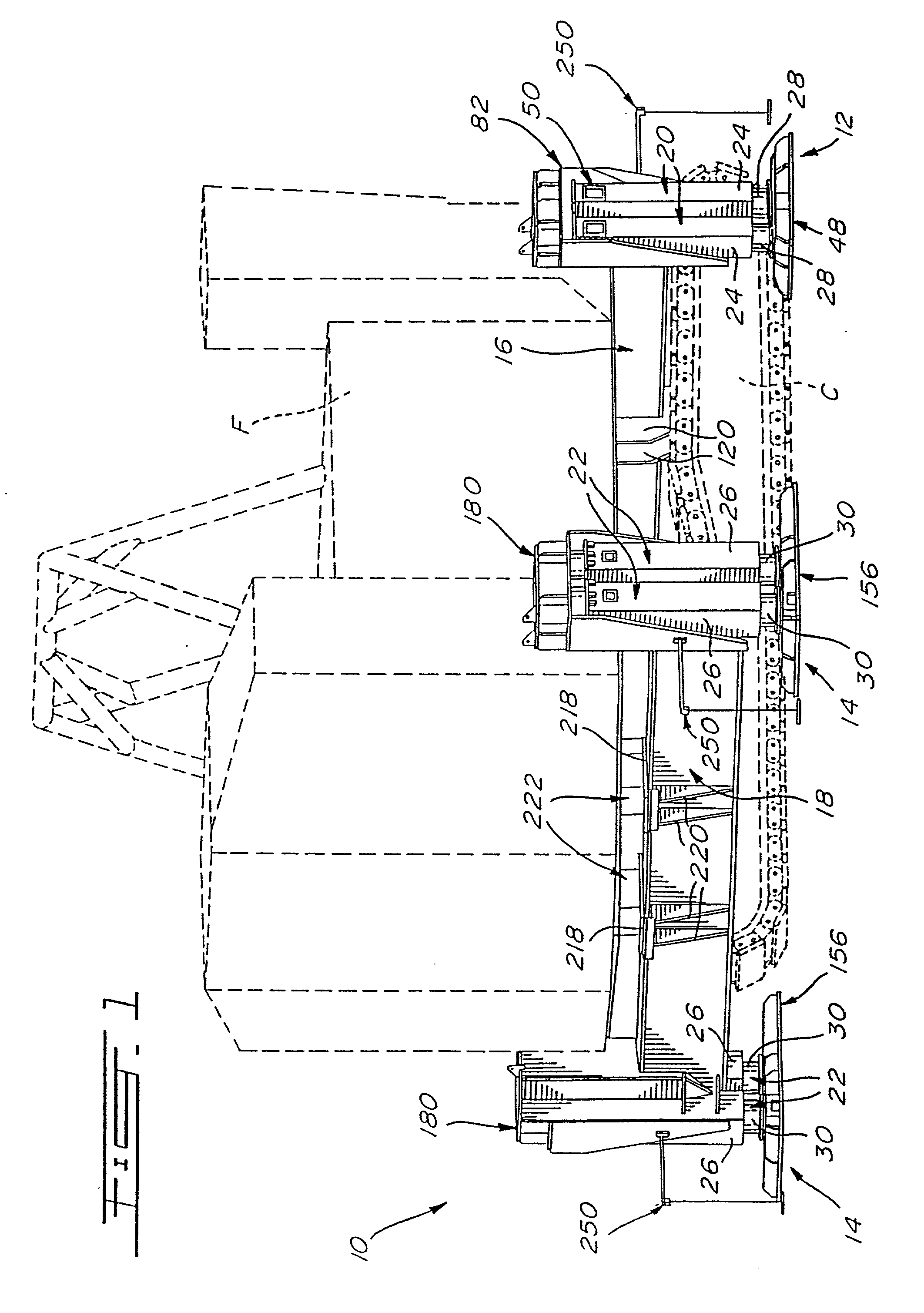
[0046] In accordance with the present invention, FIG. 1 illustrates a shovel lifting device 10 which is used to lift the revolving frame F of a mechanical shovel so as to disengage the revolving frame F from the shaft gudgeon which extends at right angle from the center of the ring gear of the undercarriage or carbody C of the shovel to allow for repairs thereof.

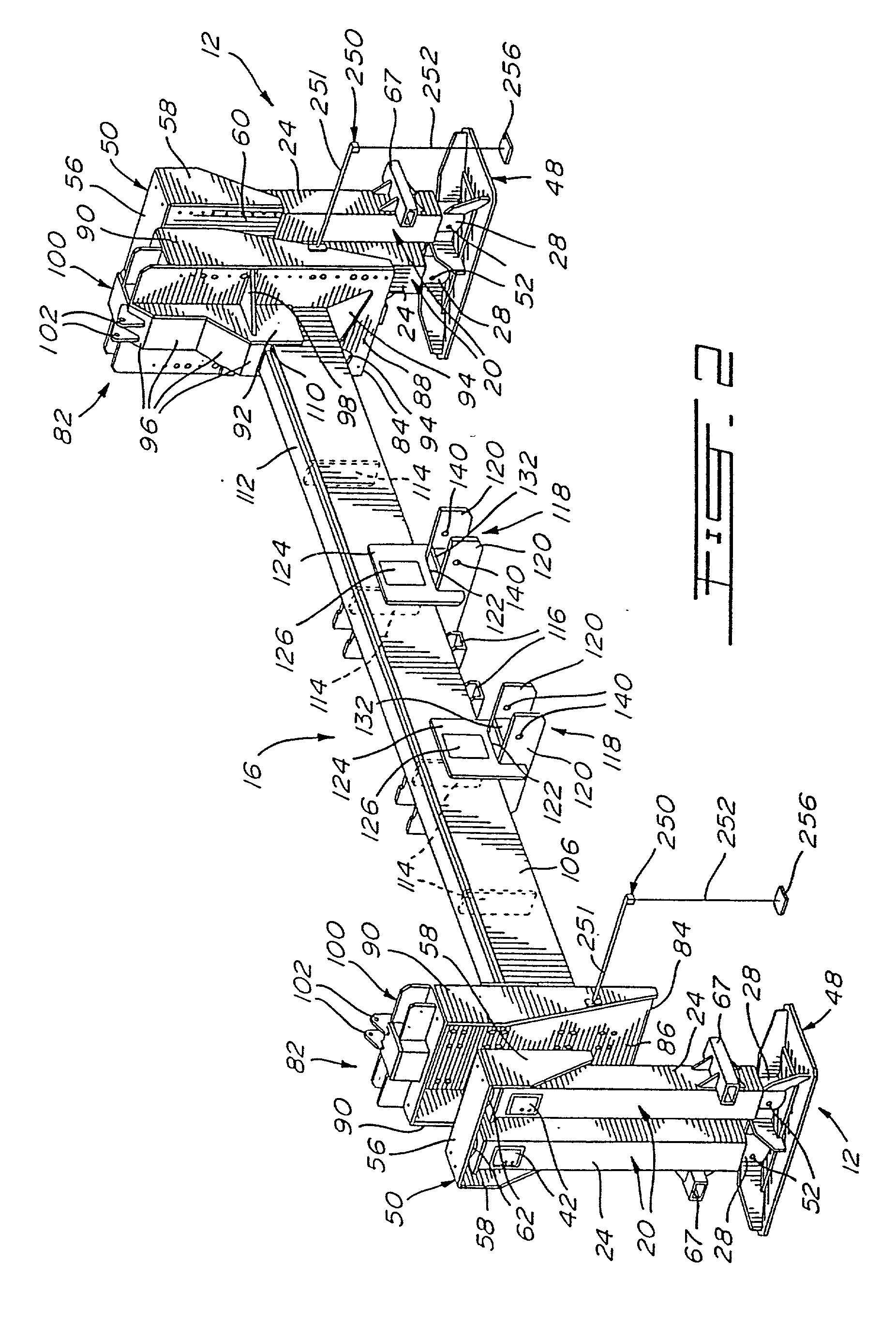
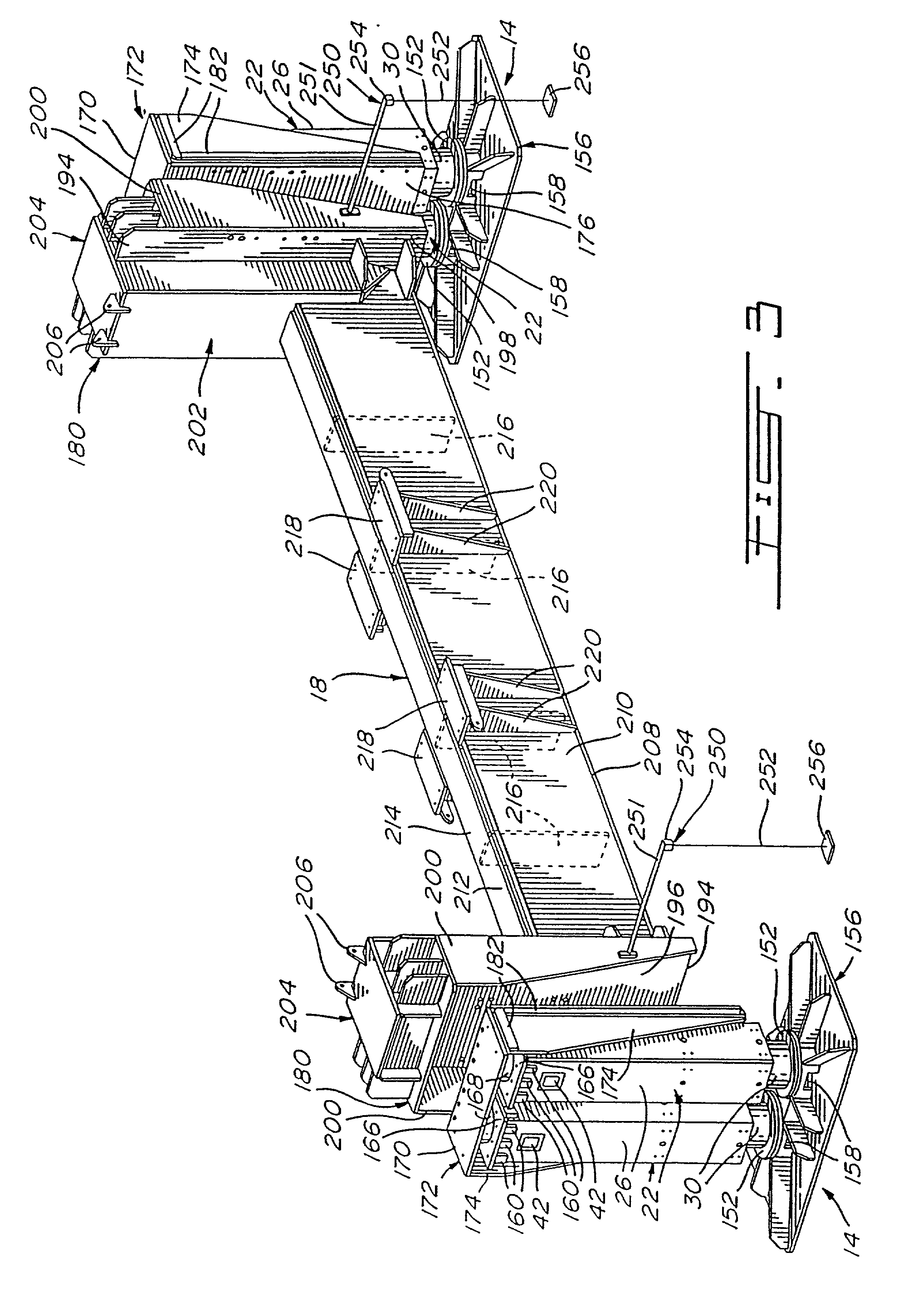
[0047] More specifically, the shovel lifting device 10 includes two front lifting units 12 and two rear lifting units 14 which are respectively located at opposed ends of front and rear lifting beams 16 and 18 which are adapted to be secured respectively under the front and rear ends of the revolving frame F of a given mechanical shovel. The shovel lifting device 10 further includes an hydraulic control unit (not shown) which is located outside of an established security perimeter to eliminate the necessity of having operators under or near the load during the lifting operation. Therefore, the chances of accident during the ...


PUM


Abstract

A universal lifting device for elevating heavy off-the-road vehicles, e.g. mechanical shovels used in mining operations, is proposed to raise the upper revolving section of the shovel and allow for its lower wheeled base to be removed with a view to attending to the maintenance, for instance, of the rotation mechanism of the shovel. The lifting device comprises front and rear lifting beams to which various type of brackets can be removably mounted to ensure a proper positioning of the front and rear lifting beams with respect to the revolving frame of different models of mechanical shovels. Front and rear lifting points are provided to control the vertical displacement of the front and the rear lifting beams, respectively. Typically, each such lifting point includes a pair of cylinders mounted in parallel fashion, an absolute lifting elevation detector and a piston stroke length detector which are connected to an automaton adapted to control the lifting operation of the revolving frame of the mechanical shovel.

Description

[0001] This application is a continuation of PCT / CA98 / 00496 filed May 22, 1998 designating the United States and claiming priority of Canadian Patent Application serial number 2,206,010 filed May 23, 1997.[0002] The present invention relates to lifting mechanisms and, more particularly, to a lifting device which is adapted to elevate the revolving frame of a heavy mechanical shovel from its wheeled undercarriage.[0003] Heavy vehicles, such as bucket wheel excavators or mechanical shovels, are subject to maintenance or repair work as, for instance, repairs to the ring gear of the turntable of a mechanical shovel which require that the revolving frame thereof, i.e. the upper part of the mechanical shovel, be lifted so as to disengage the same from the shaft gudgeon which extends at right angle from the center of the ring gear of the carbody, i.e. the lower part or undercarriage of the mechanical shovel. Accordingly, in a conventional method for lifting the revolving frame of a given m...

Claims


Application Information

Patent Timeline
Patent Type & Authority Applications(United States)
IPC IPC(8): B66F7/20E02F9/00
CPCB66F7/20E02F9/003
Inventor BELLEY, CHRISTIANMARINIER, SERGEBRIAND, JEAN
Owner 3991814 CANADA
Why Eureka
Try Eureka