Retaining wall block

a technology of retaining wall and module wall, applied in the direction of walls, excavations, artificial islands, etc., to achieve the effect of convenient handling and low manufacturing cos

Inactive Publication Date: 2001-06-28
MARTIN JAMES S +1
View PDF0 Cites 13 Cited by
  • Summary
  • Abstract
  • Description
  • Claims
  • Application Information

AI Technical Summary

Benefits of technology

[0007] It is another object of the invention to provide a composite masonry wall block which is relatively lightweight and easy to handle.
[0033] Referring again to FIGS. 1 and 2, the wall block 10 has a front face 11 and rear 12, top 14 and bottom 15, and opposing sides 16 and 17. According to one embodiment, the front face 11 includes vertical breaks 18 and 19 defining a center face portion 11A and opposing side face portions 11B and 11C. Preferably, the center face portion 11A has an unfinished, rough textured surface to promote the aesthetic appearance of the wall block 10. The center of the wall block 10 is hollow to reduce the overall weight of the block 10, and for convenient handling and placement of the block 10 during construction of the retaining wall "W".
[0035] Score lines 25 and 26 define respective severable areas 28 and 29, as shown in FIG. 5, which are conveniently removed, if necessary, during construction of the retaining wall "W" in order to properly position and orient the wall block 10 relative to the adjacent blocks 10' and 10". The severable areas 28 and 29 are typically removed with a hammer or other suitable tool. Preferably, the sides 16 and 17 of the wall block 10 include additional score lines 31A-31D and 32A-32D defining severable areas 32 and 33 along respective top side edges of the block 10. These areas 32, 33 can also be easily removed, as shown in FIG. 6, to form indents 34 (only one shown) for receiving ends of shear keys 20. The indents 34 cooperate with the shear keys 20 to further facilitate proper orientation of the stacked wall blocks 10, particularly when forming inward or outward curves in the retaining wall "W".

Problems solved by technology

This presents a problem in some cases where protruding structure intended to help anchor the block in position after construction restricts its placement and movement relative to the adjacent blocks.

Method used


Image

  • Retaining wall block
  • Retaining wall block
  • Retaining wall block

Examples


Embodiment Construction

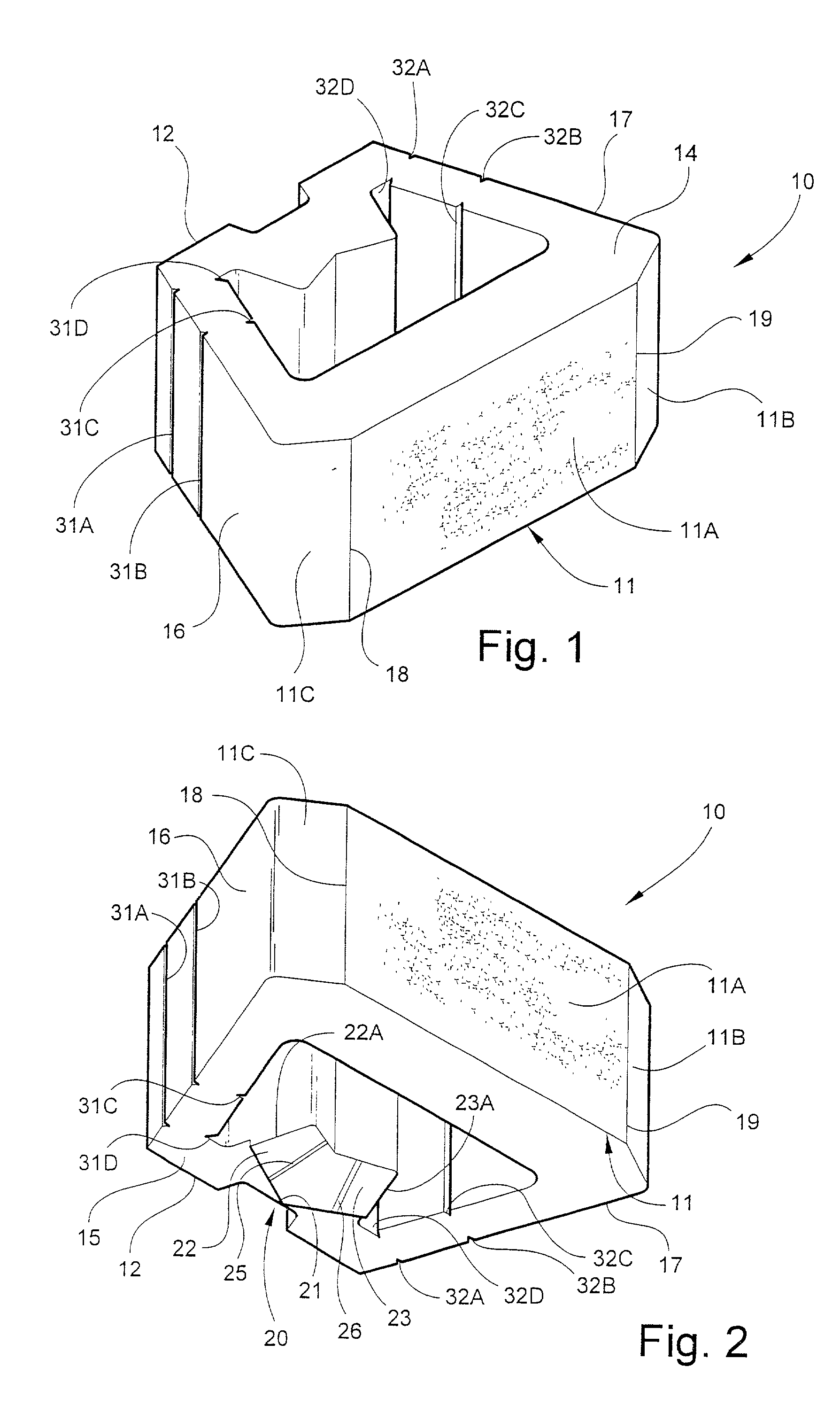
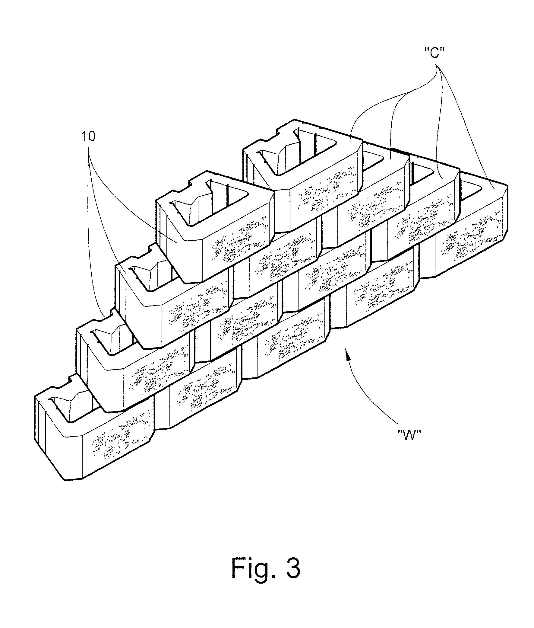
[0032] Referring now specifically to the drawings, a wall block according to the present invention is illustrated in FIGS. 1 and 2, and shown generally at reference numeral 10. As shown in FIG. 3, the wall block 10 is adapted for being assembled together with a number of like blocks in stacked courses "C" to form a retaining wall "W". The wall blocks 10 are preferably formed of molded masonry concrete.

[0033] Referring again to FIGS. 1 and 2, the wall block 10 has a front face 11 and rear 12, top 14 and bottom 15, and opposing sides 16 and 17. According to one embodiment, the front face 11 includes vertical breaks 18 and 19 defining a center face portion 11A and opposing side face portions 11B and 11C. Preferably, the center face portion 11A has an unfinished, rough textured surface to promote the aesthetic appearance of the wall block 10. The center of the wall block 10 is hollow to reduce the overall weight of the block 10, and for convenient handling and placement of the block 10 ...


PUM


Abstract

A modular wall block is adapted for being assembled together with a number of like blocks in stacked courses to form a retaining wall. The wall block includes a front face and rear, top and bottom, and opposing sides. A locking shear key extends outwardly from either of the top or bottom of the wall block, and is adapted for residing between respective adjacent sides of like blocks in an adjacent upper or lower course to anchor the wall block in position. A severable area is formed with the shear key for being removed to accommodate placement and orientation of the wall block between respective adjacent sides of like blocks in an adjacent upper or lower course.

Description

TECHNICAL FIELD AND BACKGROUND OF INVENTION[0001] This invention relates to a modular wall block and retaining wall constructed of an assembly of such blocks. The invention is particularly applicable for landscaping around residential or commercial structures to retain and preserve the surrounding soil while maintaining the aesthetics of the area. As a result of its relatively low cost, ease of manufacture and handling, concrete masonry block has emerged as one of the most popular and widely accepted material for use in constructing retaining walls. Such blocks are generally molded using standard molding systems common in the art.[0002] Conventional retaining walls formed of concrete blocks are constructed in stacked courses with the upper courses typically setback to counter the pressure of the soil acting against the wall. Due to the geographic features of the area and often for aesthetic purposes, inward and outward curves are commonly formed in the wall. When constructing the wa...

Claims


Application Information

Patent Timeline
Patent Type & Authority Applications(United States)
IPC IPC(8): E02D29/02
CPCE02D29/025
Inventor MARTIN, JAMES S.SHILLINGBURG, CURTIS W.
Owner MARTIN JAMES S
Why Eureka
Try Eureka