Shaft for light-weight golf clubs

a golf club and shaft technology, applied in the field of golf club shafts, can solve the problems of low strength and rigidity, difficult handling, and undesirable reductions in strength and rigidity of reinforcing fibers with high elasticity, and achieve the effect of preventing longitudinal cracking of materials and enhancing rigidity and strength

Inactive Publication Date: 2001-07-12
MITSUBISHI RAYON CO LTD
View PDF0 Cites 7 Cited by
  • Summary
  • Abstract
  • Description
  • Claims
  • Application Information

AI Technical Summary

Benefits of technology

0037] Additional layers can be added to the basic four layer structure discussed above. According to the invention, any number of layers can be added as long as the overall diameter and weight are in accordance with the invention. By adding the additional layers, the end of the shaft can be reinforced, diameters can be matched, rigidity and strength can be enhanced and the like.
0038] There are no special restrictions on the thickness of the first angled layer (1) as long as the thickness is a standard value generally used in FRP shafts. In a preferred embodiment, a thickness in the range of from 0.2-0.4 mm is desirable to prevent longitudinal cracking of the material, which can occur in the shaft with the removal of metal mandrel (C), which serves as a mold during manufacture.
0039] The thickness of the first angled layer (1) does not have to be uniform over the entire length of the shaft. For example, it is possible to have the thickness of the first angled layer at the small-diameter end of the shaft equal to twice the thickness of the large-diameter end of the shaft. The thickness of the layer can be used to improve various other characteristics of the shaft while preserving the objects of the invention, i.e., the flexural rigidity, flexural strength, torsional rigidity, torsional strength, and crushing strength.

Problems solved by technology

These reductions in strength and rigidity are undesirable.
However, reinforcing fibers with high elasticity generally have low strength.
However, the increased grip diameter results in a golf club shaft that is difficult to handle, making the arrangement impractical.
However, the finishing process of the FRP shaft, i.e., polishing and the like, can result in a loss in the angled layer.
Thus, FRP shafts made according to this method do not have consistent quality.
In addition, this method does not provide for a lighter FRP shaft.
As in the method previously described above, the finishing process of the FRP shaft, i.e., polishing and the like, can result in the loss of the angled layer needed to maintain torsional rigidity and torsional strength.
Thus, FRP shafts made according to this method do not have consistent quality and do not result in a lighter FRP shaft.

Method used


Image

  • Shaft for light-weight golf clubs
  • Shaft for light-weight golf clubs
  • Shaft for light-weight golf clubs

Examples


embodiment 1

[0054] The steps in forming a shaft , as shown in FIGS. 4(a)-4(h) and FIG. 5, are described below.

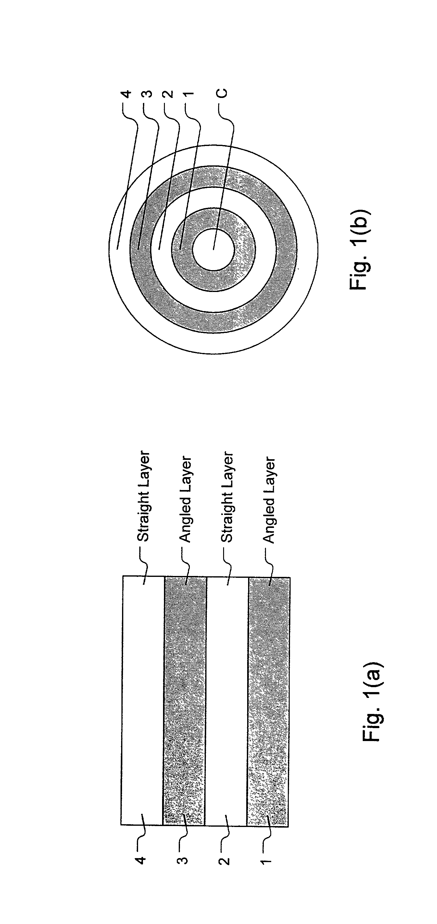
[0055] (1) A prepreg is formed from a single layer of fiber material (prepreg D in Table I). The fibers contained therein are oriented at 90 degrees relative to the longitudinal axis of the shaft. The prepreg is sheared at the small-diameter end and the large-diameter end to result in a trapezoidal shaped material as in FIG. 4(b). The trapezoidal shaped material is then wrapped around a metal mandrel to form a 90 degrees reinforcing layer of the shaft.

[0056] (2) Two prepregs are each formed from single layers of fiber material (prepreg A in Table I). The fibers contained in the first prepreg are oriented at an angle of +45 degrees relative to the longitudinal axis of the shaft. The first prepreg is sheared at the small-diameter end and the large-diameter end resulting in a trapezoidal shape. The fibers contained in the second prepreg are oriented at an angle of -45 degrees relative to t...

embodiment 2

[0077] In embodiment 2, the second angled layer is replaced with an angled layer consisting of two prepreg layers which are oriented at angles of + / -45 degrees respectively.

embodiment 3

[0078] In embodiment 3, the second angled layer is replaced with an angled layer consisting of two prepreg layers which are at angles of + / -60 degrees respectively.


PUM


Abstract

A golf club shaft is 35-50 percent lighter than a conventional shaft while maintaining the outer diameter and structural characteristics of conventional shafts. The shaft has at least four layers of fiber reinforced material. The fiber reinforced layers are from innermost to outermost: a first angled layer; a first straight layer; a second angled layer; and a second straight layer. The angled layers are formed by bonding together two materials, each with fibers aligned in different directions. The second angled layer maintains the proper strength and rigidity of the shaft while keeping the shaft as light weight as possible. Aligning the second layer's fibers at an angle of 35-75 degrees with respect to the longitudinal direction of the shaft ensures proper weight and strength characteristics of the shaft. The resulting shaft is light-weight and exhibits the flexural rigidity, flexural strength, torsional rigidity, torsional strength, and crushing strength of conventional shafts.

Description

[0001] The present invention relates to a shaft for golf clubs (hereinafter referred to simply as shaft). More specifically, the present invention relates to a shaft that is 35-50 percent lighter than conventional shafts while providing the same outer diameter and the same characteristics as conventional shafts such as flexural rigidity, flexural strength, torsional rigidity, torsional strength, and crushing strength.[0002] In one type of golf club, a fiber-reinforced composite material (hereinafter referred to as FRP) is used in forming the shaft. In this type of shaft, a fiber-reinforced fiber material is formed by lining up reinforcing fibers in a "one-directional" pre-impregnation (hereinafter referred to as prepregs) and then immersing the aligned fiber material in a resin. The shaft is then formed by wrapping the fiber-reinforced material around a tapered metal mandrel and hardening the composite in a laminated state. This type of golfclub shaft is widely used due to its high ...

Claims


Application Information

Patent Timeline
Patent Type & Authority Applications(United States)
IPC IPC(8): A63B53/10A63B102/32
CPCA63B53/10A63B59/0014A63B2209/02A63B2209/023A63B60/00A63B60/06A63B60/08A63B60/10A63B60/42A63B60/0081
Inventor ATSUMI, TETSUYATAKIGUCHI, IKUOIBUKI, TSUTOMUANAI, KATSUMI
Owner MITSUBISHI RAYON CO LTD
Why Eureka
Try Eureka