High stability optical encapsulation and packaging for light-emitting diodes in the green, blue, and near UV range

a technology of optical encapsulation and packaging, which is applied in the direction of basic electric elements, electrical apparatus, semiconductor devices, etc., can solve the problems of reducing light output, reducing the design reducing the efficiency of the diode, so as to achieve the effect of reducing the degree of yellowing attenuation and reducing the cos

Inactive Publication Date: 2001-08-02
LUMILEDS +1
View PDF0 Cites 22 Cited by
  • Summary
  • Abstract
  • Description
  • Claims
  • Application Information

AI Technical Summary

Benefits of technology

[0033] The silicone encapsulant has advantageously stable optical transmission properties in the blue through green portion of the visible spectrum (400-570 nm). Because of the stability, light attenuation caused by changes in the material's light absorption properties is not a problem.
[0045] Since the optically transmissive cover of FIG. 2 is entirely silicone material, it provides further advantageous freedom from yellowing attenuation.

Problems solved by technology

However, these materials suffer from the drawback that their optical transmissive characteristics degrade over time.
Note, incidentally, that there is also degradation due to decreased light output from the LED die itself.
By contrast, green through blue LEDs (400-570 nm) present design problems which have been more difficult to overcome.
However, shorter-wavelength LEDs are particularly subject to attenuation because of yellowing.

Method used


Image

  • High stability optical encapsulation and packaging for light-emitting diodes in the green, blue, and near UV range
  • High stability optical encapsulation and packaging for light-emitting diodes in the green, blue, and near UV range

Examples


first embodiment

[0036] FIRST EMBODIMENT--FIG. 2

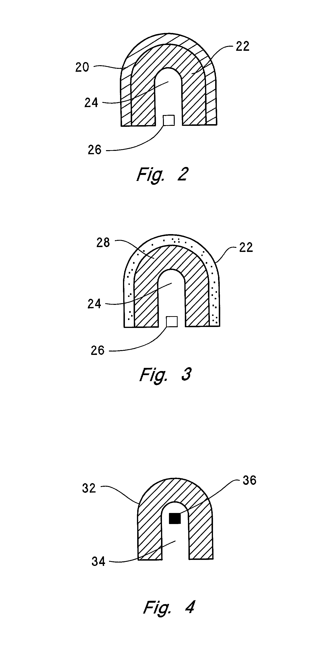
[0037] FIG. 2 is a cross-sectional view of an LED optically transmissive cover structure, in accordance with a first embodiment of the invention.

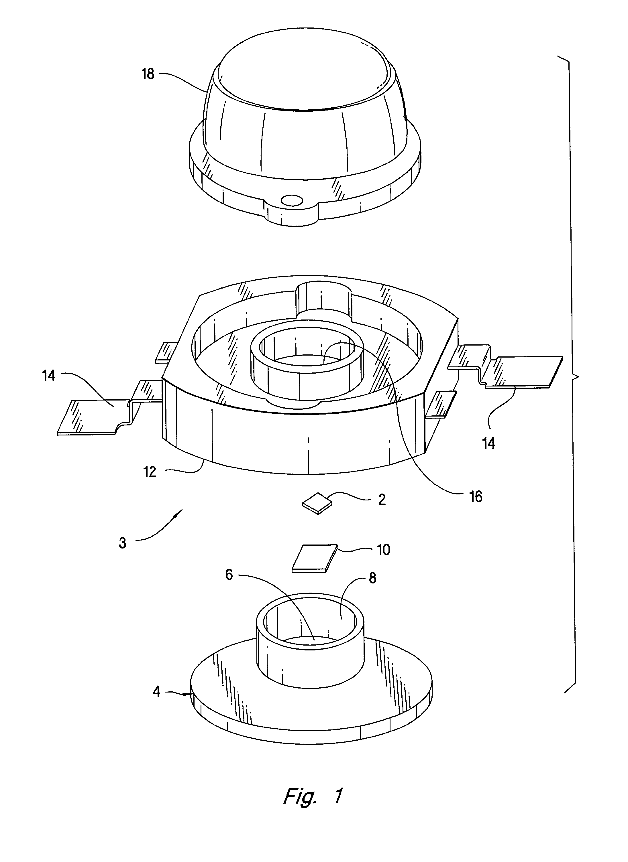
[0038] Since it is common for LED covers to be shaped as lenses, the shape is given as a convex dome. Other shapes, however, will be known to those skilled in the art. Also, the position of the LED die is indicated, but it will be understood that leads and a suitable bed arrangement are also provided.

[0039] FIG. 2 shows an LED cover configured as per a first preferred embodiment of the invention. A hard outer shell 20 is suitably shaped, e.g., as a lens. The shell may be made of any suitable optically transmissive material, preferably a stable material such as cyclic-olefin copolymers or other optical plastics, glasses, ceramics, or other transparent materials such as Aluminum Oxide.

[0040] Inside the shell 20, a quantity of softer, resilient material 22 is provided. In accordance with the invention, the materi...

second embodiment

[0042] SECOND EMBODIMENT--FIG. 3

[0043] In the second embodiment of the invention, shown in FIG. 3, an LED die 26 (in the green-to-near UV wavelength range) is disposed inside a space 24, as before. Surrounding the LED die 26 is a structure including a hard outer shell and a softer interior. The interior is again a quantity of silicone material 28, such as a gel, similar to the material 22 of FIG. 2.

[0044] In this case, however, there is an outer shell 30 made of silicone material. Preferably, the outer shell 30 is a harder, more rigid silicone formulation than that of the material 28, to give the desired rigidity and structural integrity to the LED component.

[0045] Since the optically transmissive cover of FIG. 2 is entirely silicone material, it provides further advantageous freedom from yellowing attenuation.

third embodiment

[0046] THIRD EMBODIMENT--FIG. 4

[0047] In yet another embodiment of the invention, the optically transmissive cover includes only a single layer of material.

[0048] As shown in FIG. 4, a cover made of a single, thick layer 32 of silicone material surrounds a cavity 34, in which an LED die 36 is disposed.


PUM


Abstract

An LED component is provided, with light emission in the green-to-near UV wavelength range. The light-emitting semiconductor die is encapsulated with one or more silicone compounds, including a hard outer shell, an interior gel or resilient layer, or both. The silicone material is stable over temperature and humidity ranges, and over exposure to ambient UV radiation. As a consequence, the LED component has an advantageously long lifetime, in which it is free of "yellowing" attenuation which would reduce the green-to-near UV light output.

Description

[0001] The invention generally relates to the field of Light-Emitting Diode (LED) technology. More specifically, the invention relates to LED packaging and encapsulation.[0002] An LED component essentially comprises an LED chip (a piece of semiconductor material with appropriate wire leads) and a package (typically a substantially transparent material, configured in a dome shape, the dome acting as a lens for the emitted light).[0003] The package must be rigid enough, at least on its exterior, to make the LED component structurally sound. On its interior, however, the package must be soft or resilient enough in the vicinity of the LED chip, that mechanical stresses do not damage the LED chip or the wire leads. Throughout, the transparent material of the package must keep light attenuation as small as possible, and must not adversely affect the spectrum of light which is emitted from the LED component.[0004] Conventionally, it has been necessary to compromise between these different ...

Claims


Application Information

Patent Timeline
Patent Type & Authority Applications(United States)
IPC IPC(8): H01L33/62H01L33/64
CPCH01L33/62H01L2924/0002H01L2924/00
Inventor CAREY, JULIAN A.COLLINS, WILLIAMS DAVID IIIPOSSELT, JASON L.
Owner LUMILEDS
Why Eureka
Try Eureka