
Vibrator appliance particularly useful for dialysis

a vibrator and dialysis technology, applied in the field of vibrator appliances, can solve the problems of increasing the risk of infection, disturbing the daily routine of the subject, etc., and achieve the effect of good results

Inactive Publication Date: 2001-08-09
ZICHERMAN YEHUDA
View PDF0 Cites 9 Cited by
  • Summary
  • Abstract
  • Description
  • Claims
  • Application Information

AI Technical Summary

Benefits of technology

[0006] According to one aspect of the present invention, there is provided an appliance to enhance the rate of removal of solutes during a peritoneal dialysis treatment of a subject, comprising: a holder to be applied to the subject; and at least one vibrator device carried by the holder at a location thereof to engage the subject's abdomen and to apply localized, inwardly-directed mechanical vibrations thereto at a frequency of 1-15 Hz.
[0009] According to another aspect of the invention, there is provided a method of administering a peritoneal dialysis treatment to a subject comprising a vibration session including: instilling a dialysate solution into the peritoneal cavity of the subject; applying external localized mechanical vibrations to the front side of the abdomen of the subject at a frequency of 1-15 Hz and an amplitude of 1-20 mm; and draining the dialysate solution from the subject's abdominal cavity. As indicated above, and as will be more fully described below, surprisingly good results were obtained when the mechanical vibrations were applied, at a frequency of 2-6 Hz and at a amplitude of 5-10 mm, especially when two vibrator heads were used engaging the front side of the subject's abdomen on opposite sides of its center line and oriented to direct mechanical vibrations to the central region of the subject's abdominal cavity.

Problems solved by technology

This relatively large number of sessions greatly disturbs the daily routine of the subject.
It also increases the risk of infection.

Method used


Image

  • Vibrator appliance particularly useful for dialysis
  • Vibrator appliance particularly useful for dialysis
  • Vibrator appliance particularly useful for dialysis

Examples


Embodiment Construction

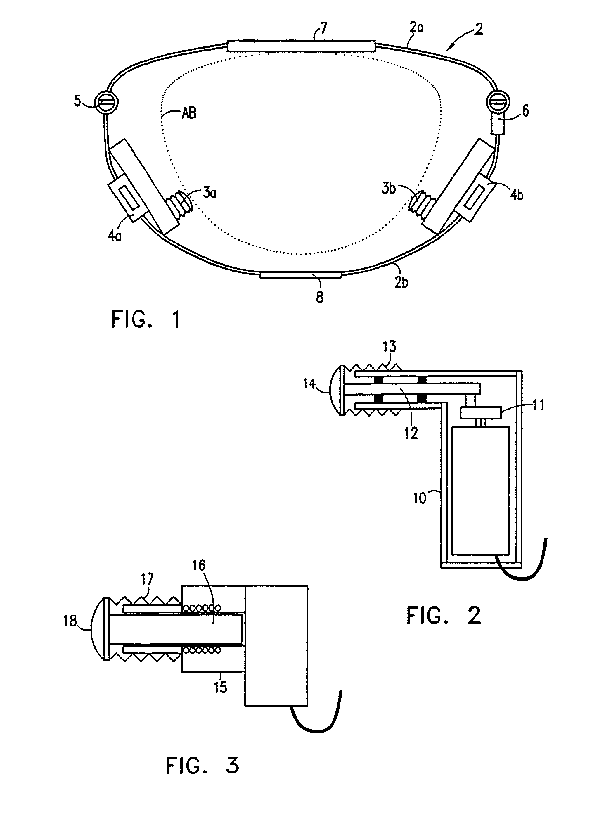
[0031] The vibrator appliance illustrated in FIG. 1 includes a holder 2 of a closed loop configuration to enclose the wearer's abdomen, indicated by broken lines AB. Holder 2 carries two vibrators 3a, 3b, each slidably mounted on the holder by a slide 4a, 4b, to enable each vibrator to be located so as to apply mechanical vibrations to opposite sides of the abdomen of the subject.

[0032] Holder 2 includes a back frame 2a, and a front frame 2b mounting the two vibrators 3a, 3b. One end of front frame 2b is pivotal, by hinge 5, to the respective end of the back frame 2a for opening and closing the holder. The opposite end of front frame 2b is lockable to the respective end of the back frame 2a by a lock, schematically shown at 6, for locking the holder in its closed condition. Both the back frame 2a and the front frame 2b include width-adjusting means, as shown at 7 and 8, respectively, for adjusting the size of the holder to fit persons of different sizes. Such width adjustment means ...


PUM


Abstract

A vibrator apparatus is provided. The vibrator apparatus includes a body weight support to support the body weight of a subject. The body weight support is attached to at least one arm, which includes a first arm portion and a second arm portion. The second arm is adjustably positionable with respect to the first arm portion. The vibrator apparatus also includes a vibrator assembly mounted on the second arm portion of the arm. The second arm portion is positionable relative to the first arm portion to engage an abdominal region of the subject and apply localized inwardly-directed mechanical vibrations.

Description

FIELD AND BACKGROUND OF THE INVENTION[0001] The present invention relates to a vibrator appliance, and particularly to one useful for a peritoneal dialysis (PD) treatment. The invention also relates to a dialysis method and particularly to one utilizing the novel vibrator appliance.[0002] Peritoneal dialysis (PD) is a medical treatment administered when there is insufficient functioning of the kidneys. It is performed by inserting a sterile plastic catheter into the abdominal cavity of the subject and instilling a dialysate solution to irrigate the peritoneum such that solutes transfer across the peritoneal membrane into the dialysate solution from the blood in the mesentery capillary network. This treatment does not require a machine, such as in hemodialysis, but does require much longer periods of time in order to achieve solute removal comparable to that of intermittent hemodialysis. Such a treatment is commonly performed in an ambulatory manner as a CAPD (Continuous Ambulatory P...

Claims


Application Information

Patent Timeline
Patent Type & Authority Applications(United States)
IPC IPC(8): A61H23/02A61M1/28
CPCA61H23/0218A61H23/0254A61H2011/005A61H2023/0272A61H2023/0281A61H2201/0192A61H2201/1604A61H2201/1623A61H2201/1628A61H2201/163A61H2201/1635A61H2205/083A61M1/28A61M1/282
Inventor ZICHERMAN, YEHUDA
Owner ZICHERMAN YEHUDA
Learn More