Method and apparatus for communicating with an implantable medical device

a medical device and implantable technology, applied in the field of methods and apparatus for communicating with implantable medical devices, can solve the problems of inconvenient and expensive replacement, inability to work with the magnet within the programmer, and insufficient placement of the magnet in the proper orientation

Inactive Publication Date: 2001-08-09
MEDTRONIC INC
View PDF4 Cites 111 Cited by
  • Summary
  • Abstract
  • Description
  • Claims
  • Application Information

AI Technical Summary

Problems solved by technology

First, the magnets employed are typically relatively heavy, high strength magnets of a type not typically available other than from the IMD manufacturer, making them inconvenient and expensive to replace in the event they are lost or broken.
However, as programming systems which employ programming antennas which may be remote from the body are developed, for example as disclosed in U.S. Pat. No. 5,113,869, issued to Nappholz et al., U.S. Pat. No. 6,169,925, issued to Villaseca et al., and U.S. Pat. No. 6,167,312, issued to Goedeke, a magnet within the programmer is not workable.
Second, placement of the magnet in proper orientation and location with regard to the IMD is sometimes difficult, making the process more cumbersome than might be desirable.

Method used


Image

  • Method and apparatus for communicating with an implantable medical device
  • Method and apparatus for communicating with an implantable medical device
  • Method and apparatus for communicating with an implantable medical device

Examples


Embodiment Construction

[0020] The present invention can be implemented in any IMD having uplink and downlink telemetry capabilities. As the technology advances, IMDs become ever more complex in possible programmable operating modes, menus of available operating parameters, and capabilities of monitoring increasing varieties of physiologic conditions and electrical signals which place ever increasing demands on the telemetry transmission system. It is also contemplated that the present invention may be implemented in more than one IMD implanted within the same patient to enable communication between them.

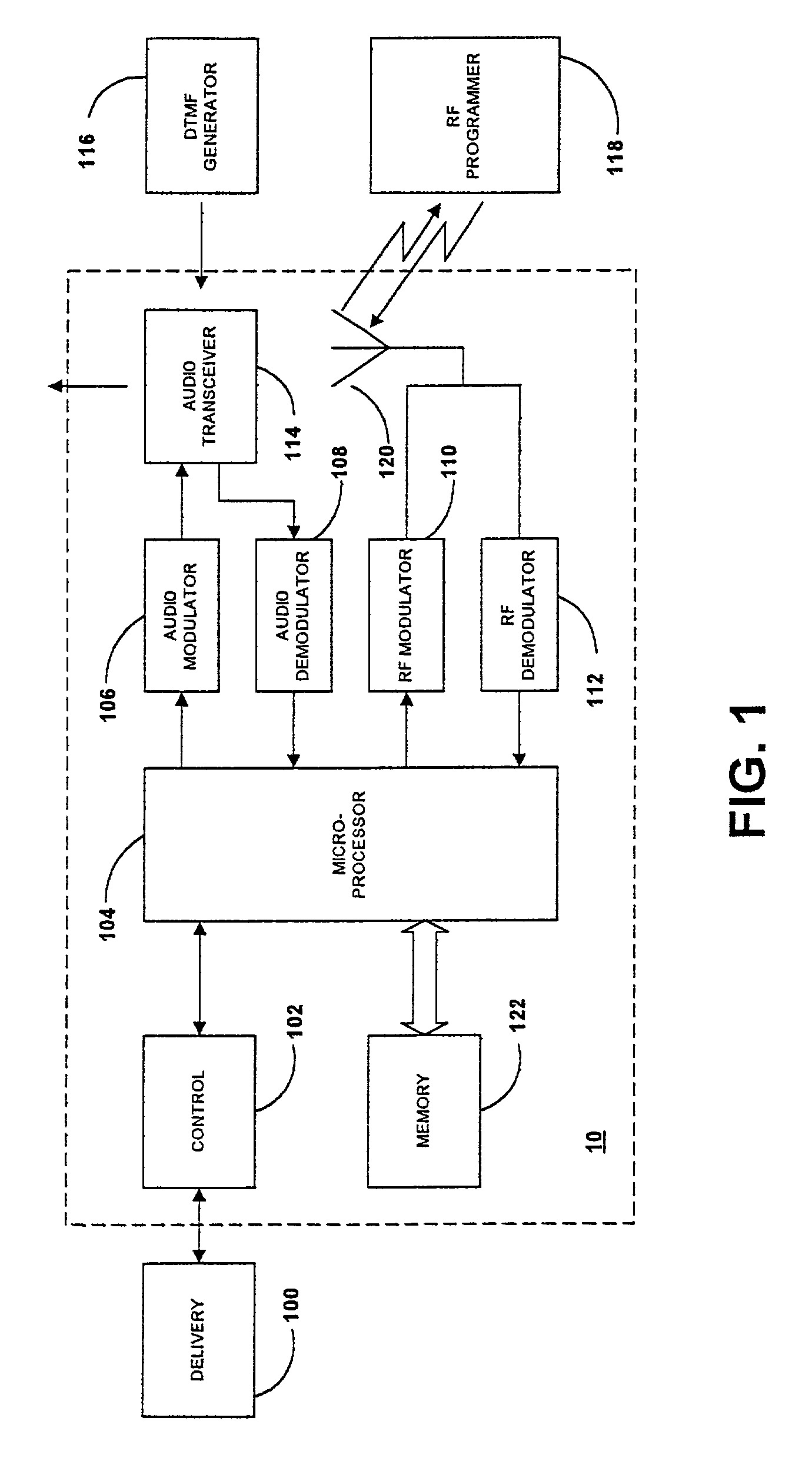
[0021] FIG. 1 illustrates a first embodiment of the invention. The IMD 10 includes a control mechanism 102 for controlling one or more operations of the IMD, which may include provision of one, or more desired therapies and / or monitoring one or more physiologic parameters within the patient, coupled to a mechanism 100 for delivering the desired therapies and / or sensing the physiologic parameters to be moni...


PUM


Abstract

Uplink and downlink telemetry between an implantable medical device (IMD) telemetry transceiver and an external medical device (EMD) telemetry transceiver used by a patient or health care provider is facilitated by the communications system of the present invention. The IMD provides a therapy and/or measures physiologic conditions of the patient for use in formulating a therapy and/or for storage in IMD memory for later uplink telemetry transmission. The patient causes the EMD to emit encoded dual tone multiple frequency (DTMF) tones that are detected by an audio receiver of the IMD to enable uplink and downlink telemetry transmissions in a telemetry or communication session. Then, the patient formulates a message via a message entry mechanism of the EMD that communicates an instruction or query to the IMD. The downlink message is optionally displayed by an EMD display as it is composed by the user and is then downlink telemetered to the IMD. A responsive uplink message from the IMD is uplink telemetered, received by the EMD telemetry transceiver, stored in EMD memory and displayed by EMD display. The EMD optionally includes a DSVD/modem module for either connection to a telephone line or a cellular telephone receiver in a variety of ways that can provide two-way voice communication between the patient and a remote care provider as well as transmission of uplink telemetered IMD and patient data to a remote EMD. The IMD may further include an audio tone generator for generating a tone or series of tones indicative of operation or status of the IMD that can be heard by the patient or received and displayed by the IMD. The DTMF tones can also be employed to alter an IMD operation.

Description

[0001] This application is a continuation-in-part of U.S. patent application Ser. No. 09 / 395,925 filed Sep. 14, 1999, for METHOD AND APPARATUS FOR COMMUNICATING WITH AN IMPLANTABLE MEDICAL DEVICE in the names of Steven H. Goedeke and Charles H. Dudding, Jr.[0002] The present invention relates generally to the field of implantable (or implanted) medical devices, and more particularly to uplink and downlink telemetry between an implantable medical device (IMD) telemetry transceiver and an external medical device (EMD) telemetry transceiver.[0003] At present, a wide variety of IMDs are commercially released or proposed for clinical implantation that are programmable in a variety of operating modes and are interrogatable using RF telemetry transmissions between the IMD and an externally located EMD. The terms "telemeter", "telemetry transmission" and the like are intended to embrace any action and manner of communicating and conveying patient data and downlink telemetry data between the...

Claims


Application Information

Patent Timeline
Patent Type & Authority Applications(United States)
IPC IPC(8): A61N1/08A61N1/372
CPCA61N1/08A61N1/37217A61N1/37258Y10S128/904G16H40/67
Inventor GOEDEKE, STEVEN D.DUDDING, CHARLES H.
Owner MEDTRONIC INC
Why Eureka
Try Eureka