Image encoding apparatus, image decoding apparatus, image encoding method, image decoding method, image encoding program recording medium and image decoding program recording medium

a technology of image encoding and image encoding, applied in the direction of color television with bandwidth reduction, instruments, television systems, etc., can solve the problems of inability to largely improve the compression rate by allowing the visually less important picture quality degradation, and the inability to reverse encoding, etc., to achieve less picture quality degradation

Inactive Publication Date: 2001-08-23
SOVEREIGN PEAK VENTURES LLC
View PDF0 Cites 19 Cited by
  • Summary
  • Abstract
  • Description
  • Claims
  • Application Information

AI Technical Summary

Benefits of technology

0407] whereby the pixels of smaller prediction probability are encoded with priority, resulting in that the ...

Problems solved by technology

Though it is known that DCT enables encoding by a small number of bits, it has own problems in that it needs high-precision multiplication, resulting in complicated calculation, and in that the reversible encoding is impossible.
However, the prior art technology has not taken into account the encoding of objects having arbitrary shapes.
Though MMR encoding is a representative one of the reversible (loss-less) encoding as described above, because of the reversibility, it is impossible to largely improve the compression rate by allowing the visually less-important picture-quality degradation.
In addition, MMR is an intra-frame encoding method, and does not take into account the improvement of the compression rate by utilizing the inter-frame correlation.
Accordingly, the encoding efficiency is good when the change of the pixel value happens along the scanning line, but the encoding efficiency is bad when the change of the pixel value does not happen along the scanning line.
Further, ...

Method used


Image

  • Image encoding apparatus, image decoding apparatus, image encoding method, image decoding method, image encoding program recording medium and image decoding program recording medium
  • Image encoding apparatus, image decoding apparatus, image encoding method, image decoding method, image encoding program recording medium and image decoding program recording medium
  • Image encoding apparatus, image decoding apparatus, image encoding method, image decoding method, image encoding program recording medium and image decoding program recording medium

Examples


embodiment 1

[0523] An image encoding apparatus according to a 1st embodiment of this invention performs efficient encoding in prediction encoding by selecting difference values having short code lengths within the given range.

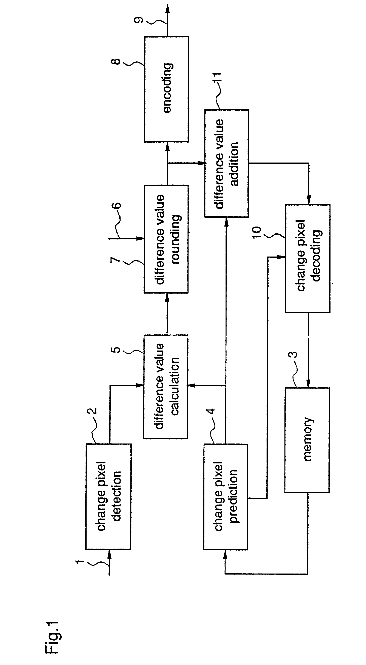
[0524] FIG. 1 is a block diagram showing the structure of the image encoding apparatus according to the 1st embodiment of this invention. In the figure, 1 indicates an input signal, which is input to the image encoding apparatus as a two-valued image signal. 2 indicates a change pixel detector which detects pixels changing pixel values in the input signal 1 and outputs the detected change pixels. 3 indicates a memory which temporarily stores already encoded and decoded image signals which are to be used as reference images. 4 indicates a change pixel predictor which predicts change pixels output by the change pixel detector 2 based on pixels changing pixel values of the reference image, and outputs predicted change pixels. As a prediction method used by the change pixel pr...

embodiment 2

[0534] An image encoding apparatus according to a 2nd embodiment of this invention performs processes, adaptively switching an encoding based on prediction from a particular frame and an encoding based on prediction from a reference frame with motion compensation.

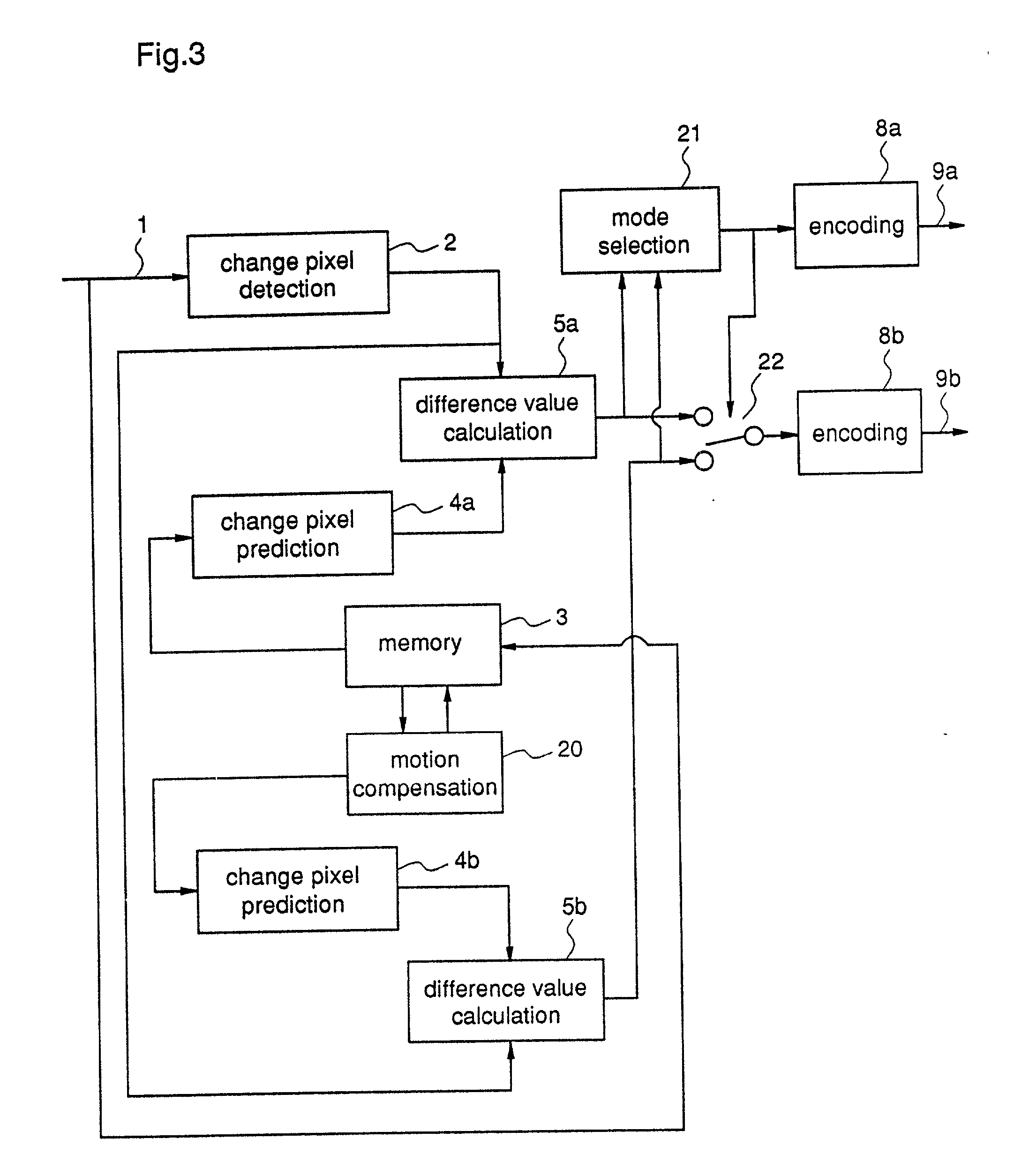
[0535] FIG. 3 is a block diagram showing the structure of the image encoding apparatus according to the 2nd embodiment. In the figure, 20 indicates a motion compensation unit which generates reference pixel values for the already encoded and decoded image signal of a reference frame by performing motion compensation. 21 indicates a mode selector which compares the difference value when prediction is carried out based on the image signal of the particular frame, with the difference value when prediction is carried out based on the image signal of the reference frame, and then selects one of the two values which has the smaller bit number required for encoding. 22 indicates a switching unit which selects the difference value ...

embodiment 3

[0547] An image decoding apparatus according to a 3rd embodiment of this invention which performs appropriate decoding for encoded signals encoded by the image encoding apparatus according to the 2nd embodiment.

[0548] FIG. 5 is a block diagram showing the structure of the image decoding apparatus according to the 3rd embodiment. In the figure, 30a and 30b correspond to the encoded signals 9a and 9b of FIG. 3, respectively. 30a indicates a signal into which the encoding mode is encoded, and 30b indicates a signal into which the difference value is encoded. 31a indicates a decoder which decodes the signal into which the encoding mode is encoded and obtains a predicted mode signal. 31b indicates a decoder which decodes the signal into which the difference value is encoded and obtains a decoded difference value signal. 32 indicates a switching unit which switches the predicted values of change pixels in response to the predicted mode signal obtained by the decoder 31a. 34 indicates a de...


PUM


Abstract

It is an object to encode an image signal or a shape signal more efficiently than the prior art. As a means to accomplish the object, the change pixel detector 2 receives the input signal 1 as an input signal and detects the pixel which changes the two-valued pixel value. Further, the change pixel predictor 4 also reads out the reference image stored in the memory 3, and predicts the change pixel of the particular input signal. The difference value calculator 5 subtracts the output of the change pixel predictor 4 from the output of the change pixel detector 2. The difference value rounder 7 compares the tolerance value e and the prediction error D, and outputs x which requires the minimum bit number for being encoded in the value D-e<=x<=D+e. The output of the difference value rounder 7 is encoded by the decoder 8 to become the encoded signal 9. Also, the output of the difference value rounder 7 is added in the difference value adder 11 to the predicted pixel 4 of the predicted pixel predictor 4, whereby the change pixel is calculated, and in the change pixel decoder 10, the respective pixels from the already decoded pixel indicated by the change pixel predictor 4 to the change pixel is decoded to be stored in the memory 3.

Description

FIELD OF TECHNOLOGY[0001] This invention relates to an image encoding apparatus, an image decoding apparatus, an image encoding method, an image decoding method, an image encoding program recording medium and an image decoding program recording medium.PRIOR ART[0002] The image encoding technology has a long history. There has been established excellent standard proposals such as ITU-T H.261, ITU-T H263, ISO MPEG1 / 2 and so on. Roughly speaking, the image encoding method has two approaches: an encoding method using the orthogonal transform and a prediction encoding method encoding the error of predicted values with the use of the prediction function. Although the encoding method using the orthogonal transform needs complicated calculation, when encoded signals of small bit numbers are obtained, it is possible to keep better picture quality than the prediction encoding method. The ordinary encoding method using orthogonal transform such as JPEG, MPEG and the like utilizes the DCT(Discr...

Claims


Application Information

Patent Timeline
IPC IPC(8): G06T9/00H04N19/21H04N19/46H04N19/463H04N19/50H04N19/503H04N19/51H04N19/52H04N19/593H04N19/70
CPCH04N19/503H04N19/51H04N19/61H04N19/107H04N19/20H04N19/543
Inventor KADONO, SHINYA
Owner SOVEREIGN PEAK VENTURES LLC
Why Eureka
Try Eureka