Electrode structure of piezoelectric vibrator

Inactive Publication Date: 2001-08-30
SII CRYSTAL TECH
View PDF0 Cites 13 Cited by
  • Summary
  • Abstract
  • Description
  • Claims
  • Application Information

AI Technical Summary

Problems solved by technology

However, according to the above-described method, when the lids and the bases are formed at a wafer having a material with thermal expansion different from that of the wafer formed with the vibrators, at a time point of bonding the wafer formed with the vibrators and the bases, by a difference in the thermal expansion coefficient of the wafer formed with the vibrators and the bases, warp is caused and therefore, a large area thereof enlarging a warp amount can not be bonded.

Method used


Image

  • Electrode structure of piezoelectric vibrator
  • Electrode structure of piezoelectric vibrator
  • Electrode structure of piezoelectric vibrator

Examples


Embodiment Construction

[0017] A detailed explanation will be given of the invention in reference to the drawings as follows.

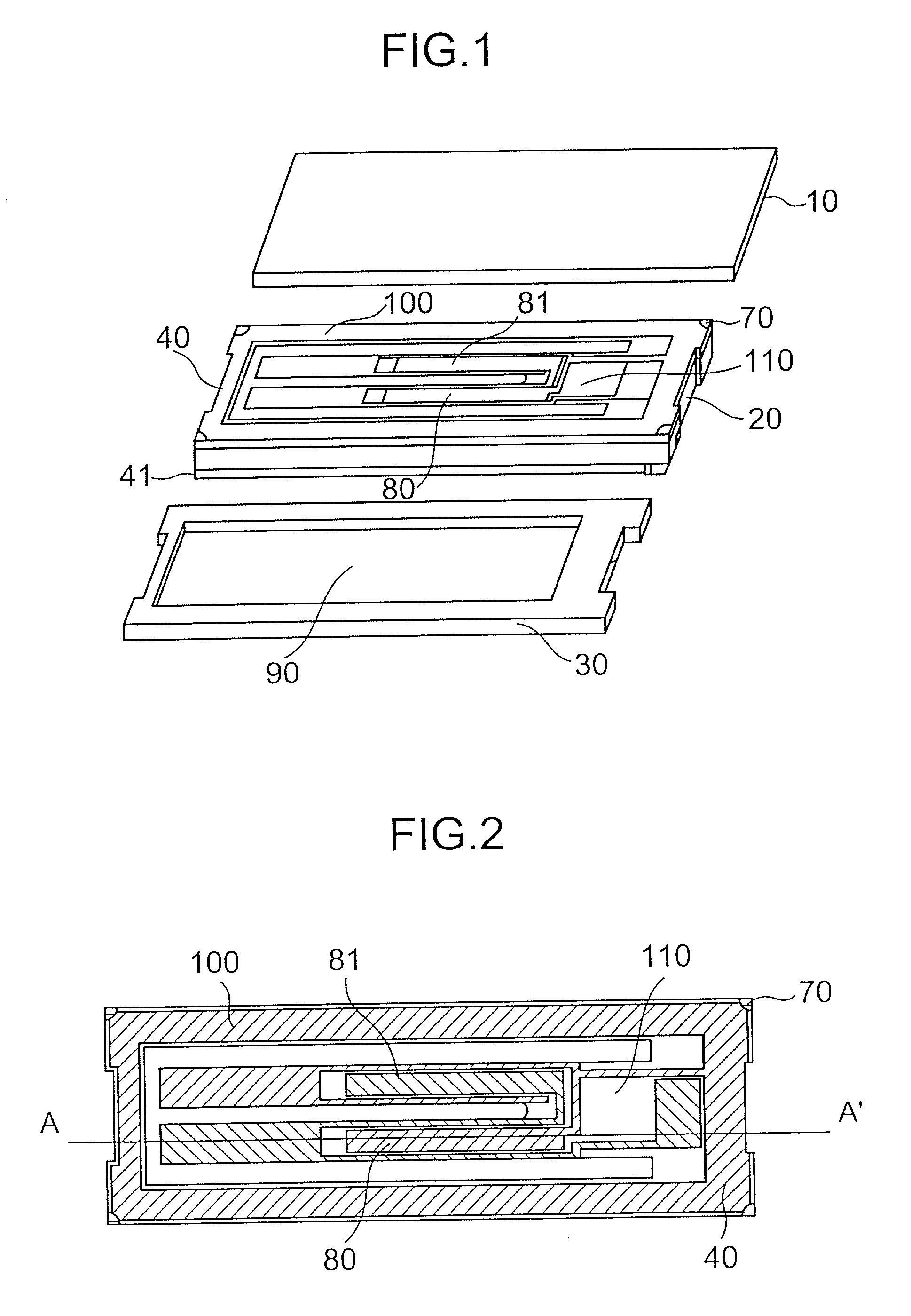
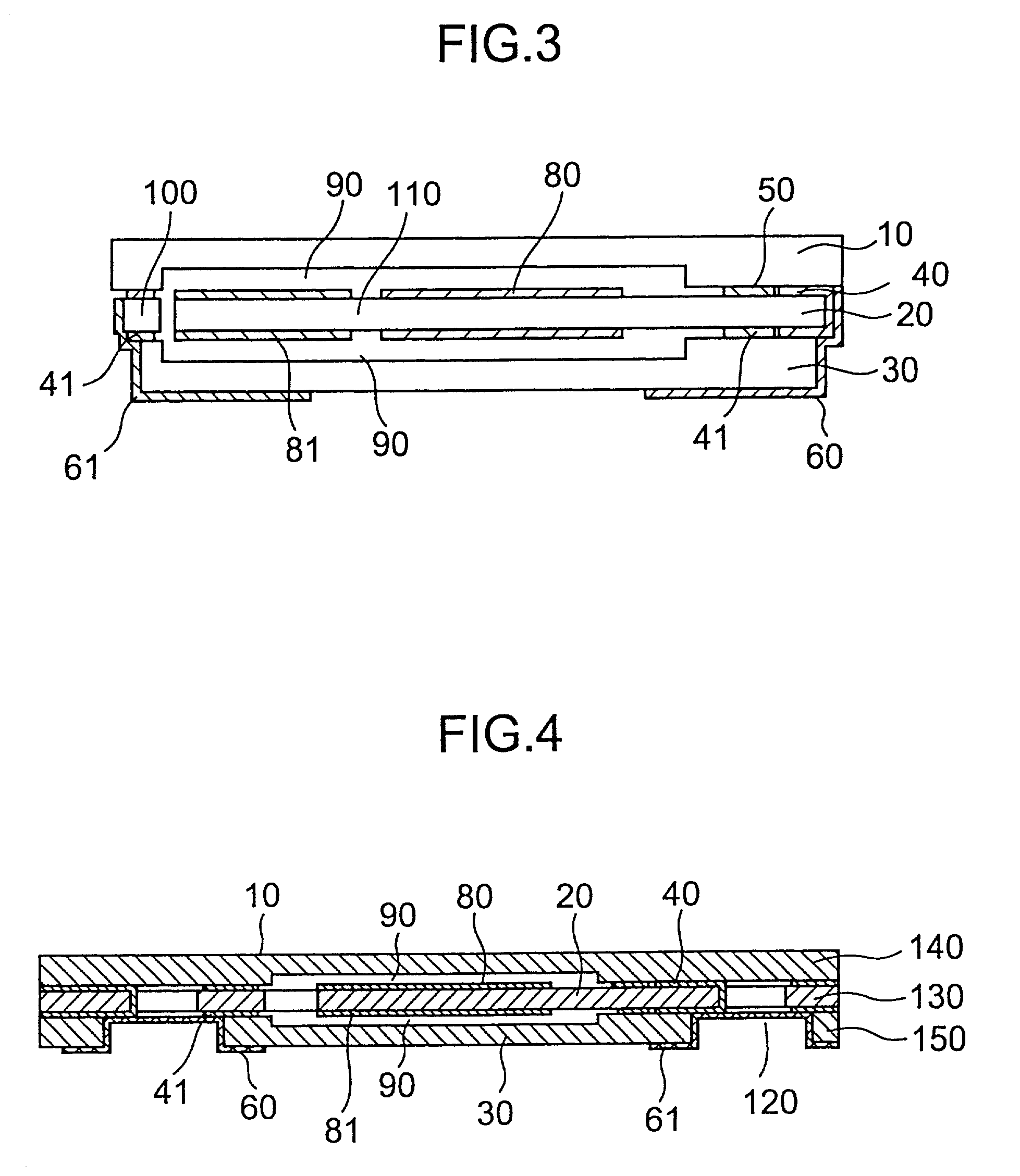
[0018] FIG. 1 is a disassembled perspective view of the invention, FIG. 2 is a top perspective view of the invention and FIG. 3 is a sectional view of a piezoelectric vibrator of the invention.

[0019] A piezoelectric vibrator of the embodiment is, for example, a quartz vibrator having a tuning fork type quartz vibrator piece 110 comprising quartz (SiO.sub.2) and, as illustrated, provided with an vibrator 20 having the quartz vibrator piece 110 and a lid 10 and a base 30 constituting a pair of lids bonded to two faces of the vibrator 20 for sealing in air tight the quartz vibrator piece 110 in an oscillatable state. As shown by FIG. 1, FIG. 2 and FIG. 3, the vibrator 20 of the embodiment includes the tuning fork type quartz vibrator piece 110 and a frame-like portion 100 integrally connected to a base end portion of the quartz vibrator piece 110 for surrounding the quartz vibrator piec...


PUM


Abstract

To provide a piezoelectric vibrator having an electrode structure capable of bonding a large area, on a quartz wafer formed with a plurality of vibrators each comprising a quartz vibrator piece and a frame, there are formed electrode patterns each including a pair of excitation electrode films on the respective quartz vibrator piece and bond films formed on the respective frame and connected to the pair of excitation electrode films and the electrode patterns are connected to each other by sputter films for shortcircuiting constituting metal films.

Description

[0001] 1. Field of the Invention[0002] The present invention relates to an electrode structure of a piezoelectric vibrator is in a portable telephone and a portable information terminal.[0003] 2. Description of Related Art[0004] As a piezoelectric vibrator of a related art, there is provided a structure in which, for example, upper and lower faces of an vibrator comprising a piezoelectric vibrator piece and an upper portion of a frame integrally formed at a base end portion of the piezoelectric vibrator piece, are provided with a pair of a lid and a base having recess portions having spaces to a degree of not hampering vibration of the piezoelectric vibrator piece.[0005] When a plurality of respective members of piezoelectric vibrators as describe above are formed on a wafer having a large area and mass-produced by a unit of the wafer, according to an electrode pattern such as an excitation electrode film formed on an individual vibration piece, in order to grasp electric properties...

Claims


Application Information

Patent Timeline
IPC IPC(8): H01L41/053H03H9/13H01L41/09H03H9/02H03H9/05H03H9/10H03H9/215
CPCH01L41/053H03H9/0595H03H9/1035H03H9/215Y10T29/42H10N30/88
Inventor ARATAKE, KIYOSHISHIRAISHI, MASAYOSHI
Owner SII CRYSTAL TECH
Why Eureka
Try Eureka