Connector and a connecting structure of circuit boards therewith

a technology of connecting structure and circuit board, which is applied in the direction of securing/insulating coupling contact members, electrical apparatus construction details, coupling device connections, etc., can solve the problems of large man-hours, large cost, and inconvenient construction

Inactive Publication Date: 2001-09-06
YAZAKI CORP
View PDF0 Cites 9 Cited by
  • Summary
  • Abstract
  • Description
  • Claims
  • Application Information

AI Technical Summary

Benefits of technology

[0031] According to the above-described structures of the present invention, the following advantages are provided.
[0052] (21) Since the circular-arc front end surface of the housing smoothly slips on the first circuit board when the housings turns about the hinges, the second circuit board can be inserted inside the connector smoothly and also both the circuit boards can be easily connected to the connector, thereby improving connecting workability and enhancing reliability in electrical connection.

Problems solved by technology

Therefore, much man-hour is required for arrangement work of the circuit assembly 98 since the circuit assembly 98 is complicated, and also the structure is not compact and the cost is fairly large.

Method used


Image

  • Connector and a connecting structure of circuit boards therewith
  • Connector and a connecting structure of circuit boards therewith
  • Connector and a connecting structure of circuit boards therewith

Examples


first embodiment

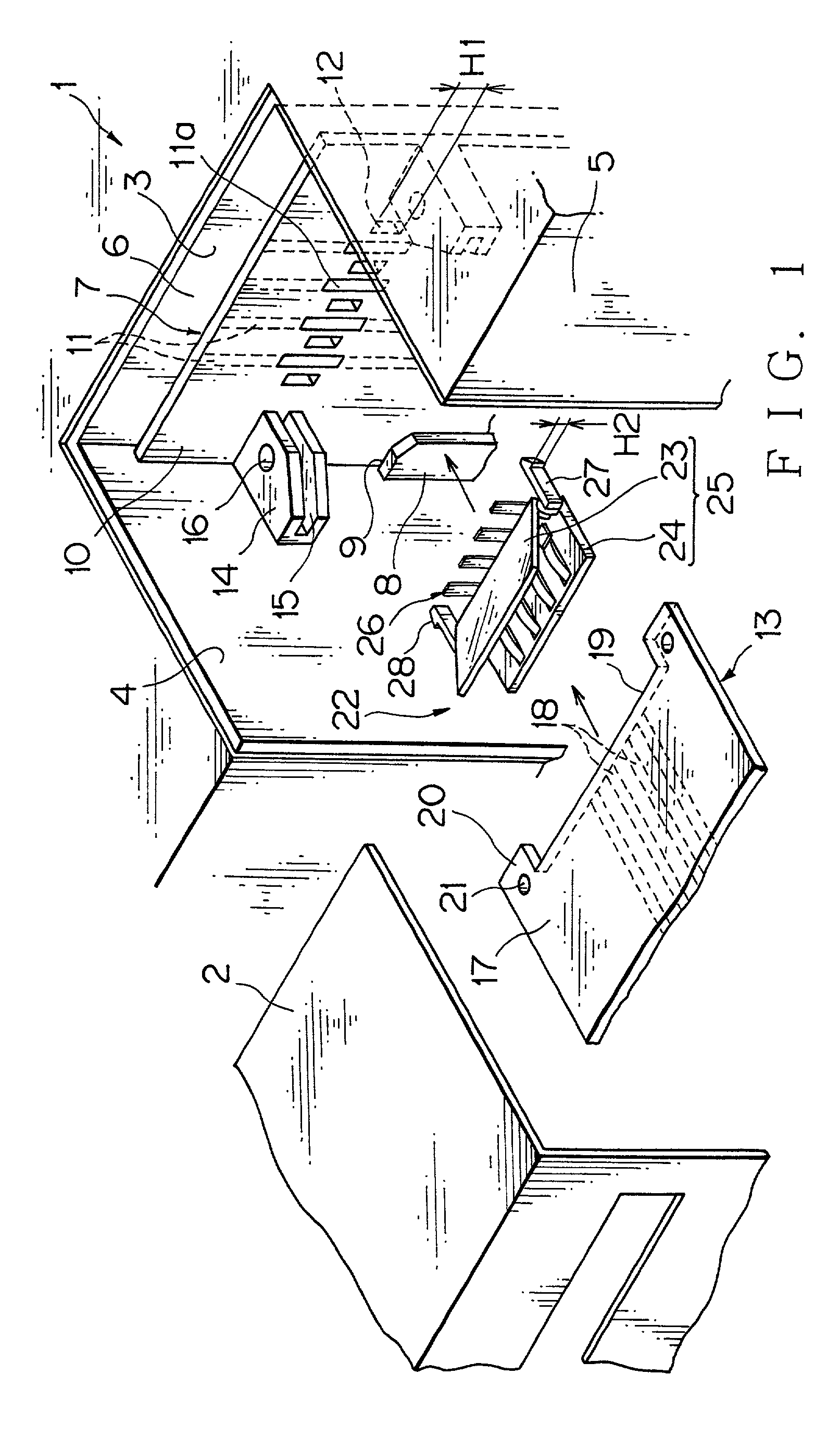
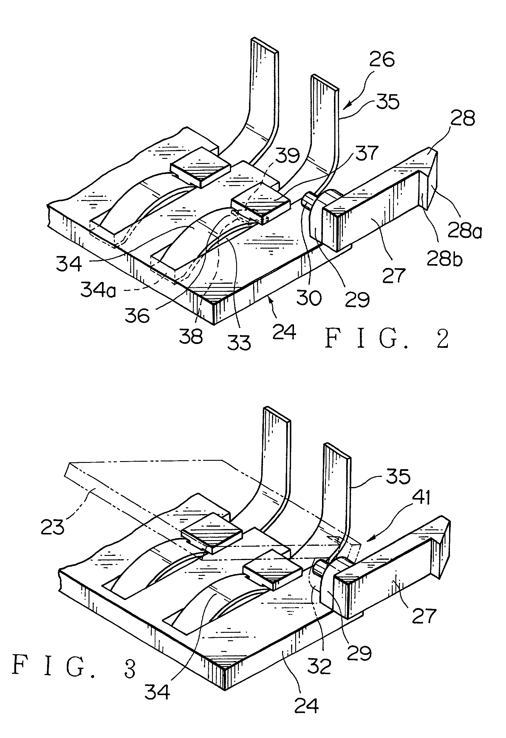
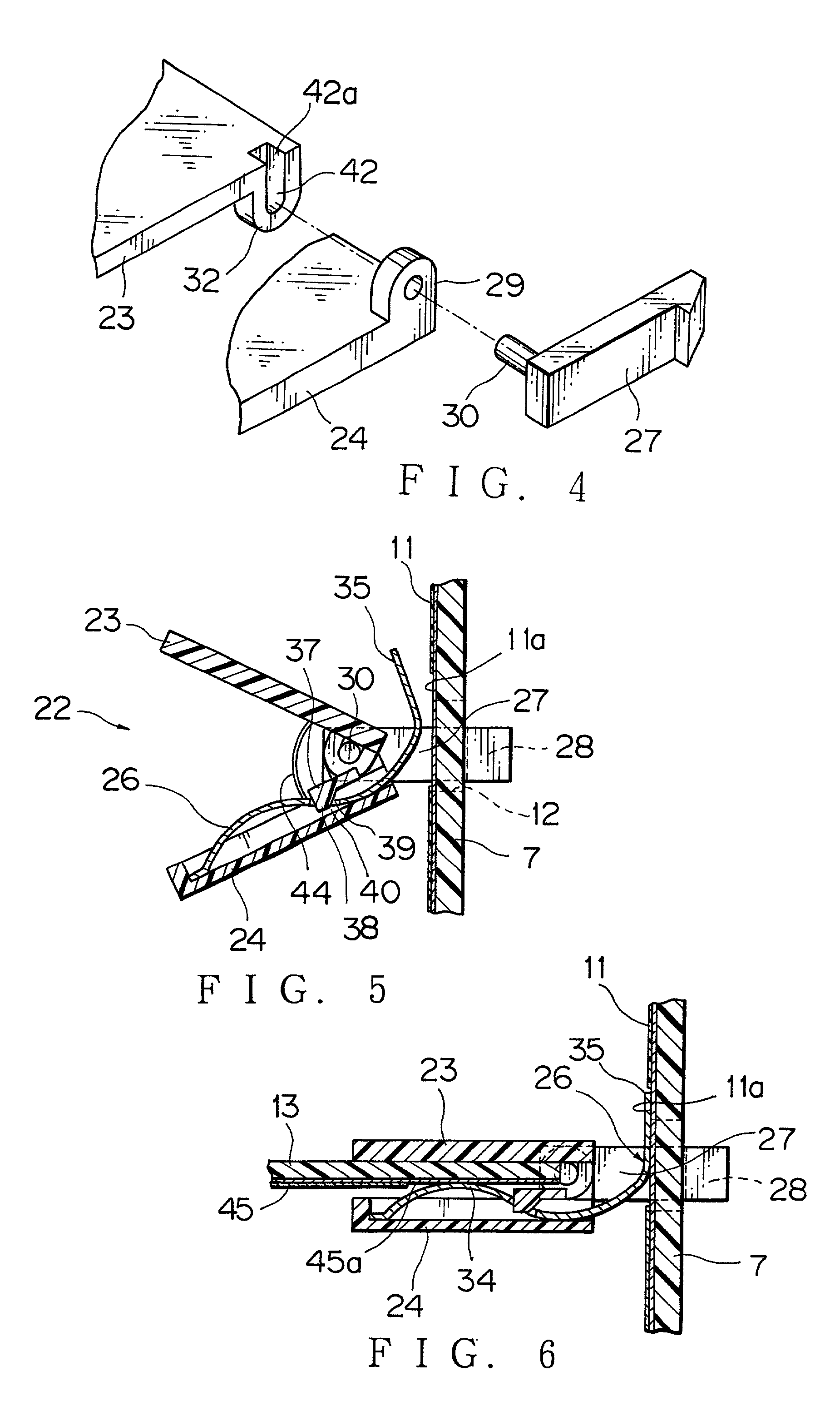
[0075] FIGS. 1-3 show a connector and a connecting structure of circuit boards therewith in accordance with the present invention. The present embodiment applies to the connection of circuit assemblies (i.e. circuit boards) and accessories of a motor vehicle. In FIG. 1, 1 designates a casing as an instrument panel core, 2 designates a cover as a cluster.

[0076] The casing 1 has a vertical rear wall 3, sidewalls 4, and flange walls 5, and a space 6 is provided among them. A first circuit board 7 that is vertically accommodated in the space 6. A first guide portion 8 is vertically provided on each of the sidewalls 4, and the first circuit board 7 slidably engages guide grooves 9 behind the respective first guide portions 8. In this embodiment, a cover 2 side, i.e. driver's side, is defined as a front side of the casing 1.

[0077] The first circuit board 7 is a circuit assembly on a side of the instrument panel and has flat circuit conductors 11 of, for example, a power circuit and / or a s...

second embodiment

[0094] FIGS. 8-14 show a connector and a connecting structure of circuit boards therewith in accordance with the present invention. In the connecting structure of the present embodiment, as shown in FIG. 8, a vertical first circuit board 112 arranged inside a casing 111 which is an instrument panel core of a motor vehicle, a horizontal second circuit board 115 to be inserted into guide portions 114, a vertical third circuit board 116 utilizing the rear board of the casing 111 and having vertical power busbars 117 are connected by means of a connector 110.

[0095] A plurality of vertical circuit conductors (printed conductors) 118 of the first circuit board 112 are signal ones. A plurality of circuit conductors (printed conductors) 119,120 on the face of the second circuit board 115 are signal and power ones. The center and the both sides of the second circuit board 115 project forward, and the distal ends of the circuit conductors 119,120 are arranged on the projecting portion 121 at ...

third embodiment

[0115] FIGS. 15-17 show a connector and a connecting structure of circuit boards therewith in accordance with the present invention.

[0116] In FIGS. 15, 51, 52, 53, and 54 designate a casing as an instrument panel core, a cover as a cluster, an accessory such as a switch unit or an audio system, and a connector connected to the accessory, respectively.

[0117] A panel 56 is vertically fixed with guide portions 57 (only one is shown) inside a space 55 of the casing 51. A first circuit board 58, to be thin and resilient, is fixed to the panel 56 by a non-shown engaging means such as a FFC (a flexible flat circuit board) and a FPC (a flexible printed circuit plate). The first circuit board 58 may be secured to the panel 56 by only an engaging plate 85 of a connector 54. A plurality of circuit conductors 59 are vertically provided on the first circuit board 58 which is a circuit assembly on a side of an instrument panel.

[0118] A second circuit board 60 is protrusively-provided on the acces...


PUM


Abstract

A connector and a connecting structure of circuit boards therewith is provided, which includes: a first circuit board; a second circuit board orthogonally arranged relative to the first circuit board; a terminal having first and second contact portions for the respective first and second circuit boards; and a housing to accommodate the terminal. An engaging member for attaching the housing to the first circuit board projects from the housing, and the first contact portion projects in a same direction as the engaging member. The engaging member is longitudinally movable at an engaging portion provided on the first circuit board. The engaging member is pivotable. The housing consists of a pair of housings turnable about a hinge, and a second contact portion of the terminal is accommodated between the housings. A groove as a positioning portion for a housing is provided. The housing consists of a fixed-side housing having the engaging member for the first circuit board and a moving-side housing movable relative to the fixed-side housing, and the terminal is accommodated in the moving-side housing. A shaft portion is provided on either one of the fixed-side housing and the moving-side housing, and a shaft engaging portion to movably engage the shaft portion is provided on the other of the fixed-side housing and the moving-side housing. A moving-side housing engaging portion is provided on the first circuit board, and an engaging portion for the moving-side housing engaging portion is provided on the moving-side housing.

Description

[0001] 1. Field of the invention[0002] The present invention relates to a connector and a connecting structure of circuit boards therewith, wherein two crossing or perpendicularly arranged circuit boards are electrically connected with a connector having surface contact-type terminals.[0003] 2. Description of the Related Art[0004] FIGS. 19, 20 show a connecting structure of a connector and a circuit assembly disclosed in Japanese Patent Application Laid-open No. 11-67340.[0005] In this structure, as shown in FIG. 19, a wiring harness 98, namely a circuit assembly, is arrange between a door panel 95 and a door trim 96 of a motor vehicle through a waterproof sheet 97, and a connector 99 of the wiring harness 98 and a connector 101 of a switch unit 100, namely one of accessories to be assembled to the door trim, are connected.[0006] As shown in FIG. 20, the connector 99 on a side of the circuit assembly projects toward the door trim 96 in a state of provisional engagement with a holder...

Claims


Application Information

Patent Timeline
Patent Type & Authority Applications(United States)
IPC IPC(8): H01R13/42H01R24/00H01R31/06H01R107/00H05K7/14
CPCH05K7/1439H01R12/721H01R12/87
Inventor WATANABE, HIROSHIKATO, MITSUNOBU
Owner YAZAKI CORP
Why Eureka
Try Eureka