Vapor -liquid ejector with a removable nozzle

Inactive Publication Date: 2001-09-13
CO GENERALE DES MATIERES NUCLEAIRES
View PDF0 Cites 14 Cited by
  • Summary
  • Abstract
  • Description
  • Claims
  • Application Information

AI Technical Summary

Benefits of technology

0055] This latter embodiment of the means arranged on the outer surface of the nozzle to deflect the driven liquid into the enlarged interstitial volume (whether the means are fitted or machined in the mass of the nozz

Problems solved by technology

This problem is particularly applicable to the portion of the nozzle which is in contact with the driven liquid.
In any event, the problem of corrosion is critical in the clearance that must be present in order to enable the remov

Method used


Image

  • Vapor -liquid ejector with a removable nozzle
  • Vapor -liquid ejector with a removable nozzle
  • Vapor -liquid ejector with a removable nozzle

Examples


Example

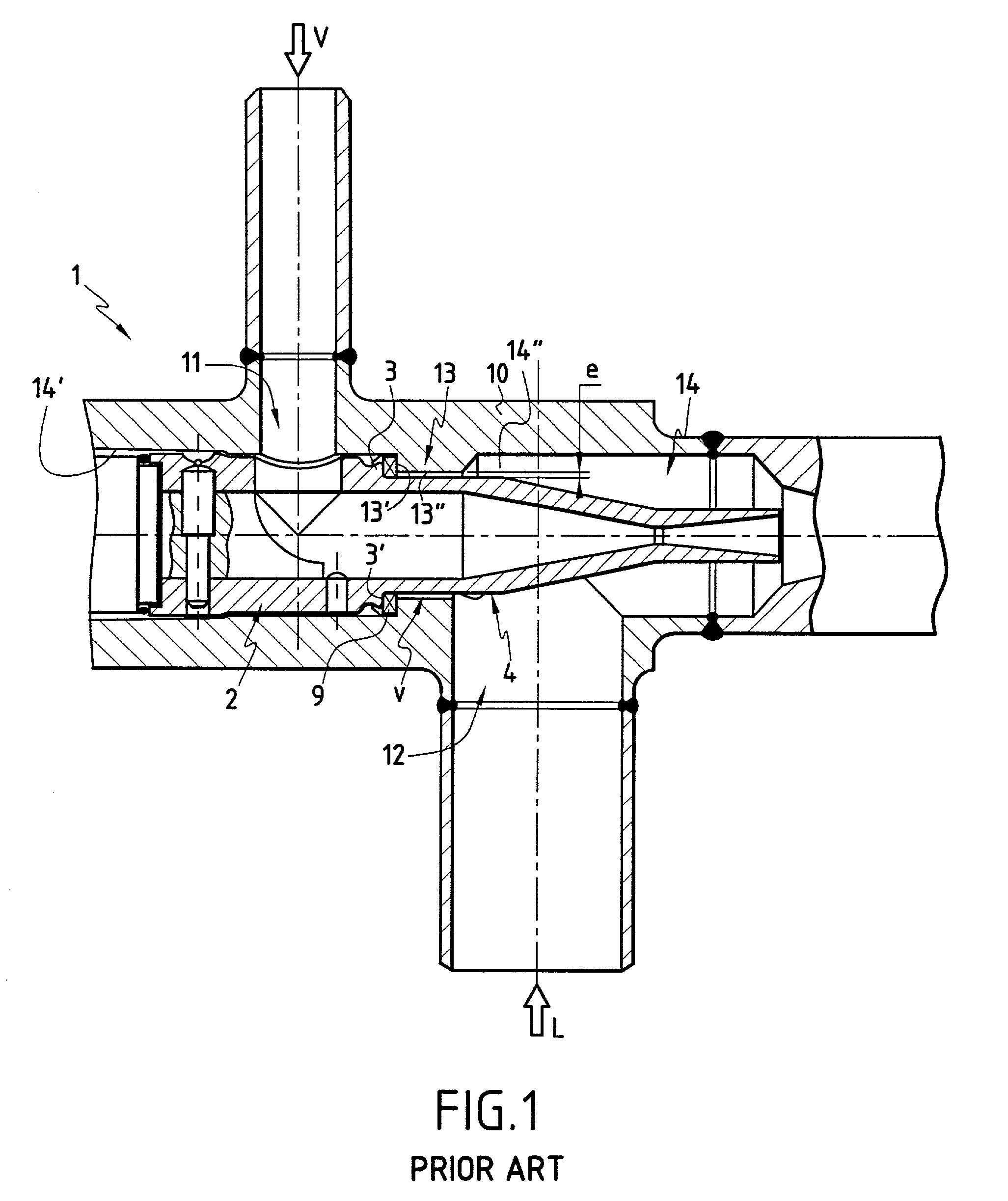
[0071] FIG. 1 is described in the introductory portion of the present description. It shows a prior art removable-nozzle vapor-liquid ejector. Said nozzle 2 is shown mounted in the recess 14 of the body 10 of the ejector. The annular interstitial volume +E,uns v corresponding to the clearance for assembling said nozzle 2 in said recess 14 is very narrow. It is of constant thickness +E,uns e generally of about 0.2 mm.

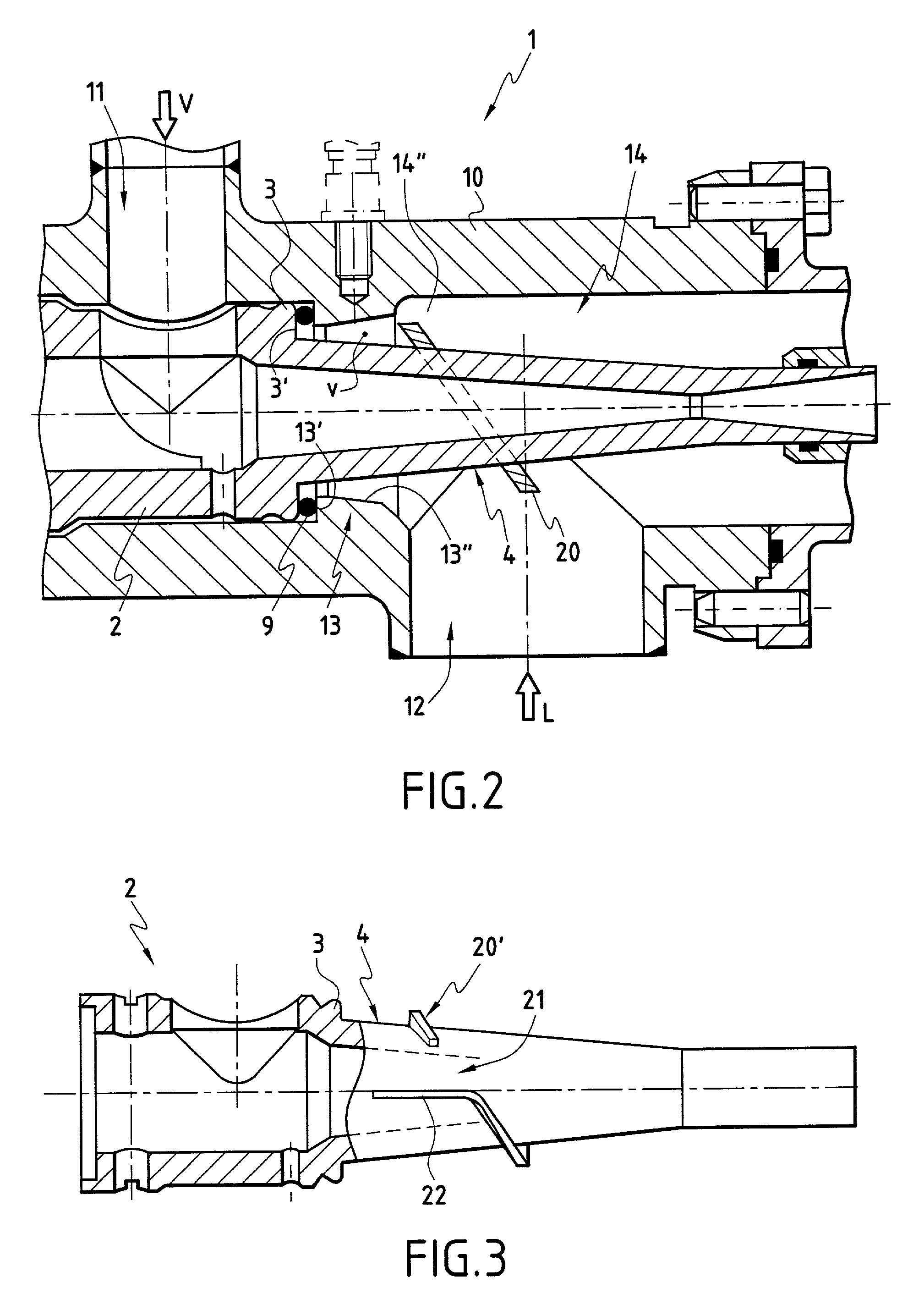
[0072] In FIG. 2, the same references are used to designate the same parts and components that are common to the prior art ejector (as shown in FIG. 1) and the ejector of the invention.

[0073] With reference to FIG. 2, it can be seen that the looked-for result of the invention is obtained:

[0074] by modifying the profile of the outer surface 4 of the nozzle 2 and the profile of the shoulder 13 of the body 10; and

[0075] by adding an elliptical washer 20 on said outer surface 4 of said nozzle 2.

[0076] The volume +E,uns v as enlarged in this way is substantially in the form o...


PUM


Abstract

The present invention provides a vapor-liquid (V-L) ejector with a removable nozzle (2) in which the internal structure has been modified and improved concerning the clearance that exists to enable said nozzle (2) to be engaged in the body (10) of said ejector (1). The invention also provides a nozzle (2) for such an ejector (1).

Description

[0001] The present invention relates to a vapor-liquid ejector with a nozzle that is removable (or dismountable).[0002] This type of device is known per se. It enables a liquid to be entrained by means of a driving fluid: namely the vapor. Said vapor passes through the nozzle of the device which transforms its pressure into speed. The nozzle is usually of the "supersonic" type having a converging-diverging profile which serves to increase outlet speed compared with that which would be obtained using a converging-only nozzle. Optimum efficiency is obtained by bringing the pressure of the vapor close to the suction pressure of the liquid. On coming into contact with the driven liquid, the vapor condenses very quickly, but not instantly. There generally remains a "dart" of vapor in the form of a converging cone at the outlet from the nozzle.[0003] The driving fluid is generally steam, but there is no a priori reason why some other kind of vapor should not be used, providing its physica...

Claims


Application Information

Patent Timeline
IPC IPC(8): F04F5/24F04F5/46
CPCF04F5/461
Inventor MIQUEL, PIERREPONCELET, FRANCOISBRETAULT, PHILIPPEMICHEL, DIDIER
Owner CO GENERALE DES MATIERES NUCLEAIRES
Why Eureka
Try Eureka