Drive device

a technology of driving device and drive shaft, which is applied in the direction of dynamo-electric machines, electric/electrostrictive devices, electric apparatus, etc., can solve problems such as restricting the application field, and achieve the effect of large stroke and large for

Inactive Publication Date: 2001-09-13
FESTO AG & CO KG
View PDF0 Cites 0 Cited by
  • Summary
  • Abstract
  • Description
  • Claims
  • Application Information

AI Technical Summary

Benefits of technology

0003] One object of the invention is to create a drive device whose characteristics are able to be varied using comparatively simple means and which in case of need renders possible performing drive movements with a large force and simultaneously a large stroke.

Problems solved by technology

While being suitable for the transmission of large forces such drives generally only perform a drive movement with relatively small force strokes.
Furthermore, there are design limitations as regards presetting the force-stroke characteristic, this restricting the field of application.

Method used


Image

  • Drive device
  • Drive device
  • Drive device

Examples


Embodiment Construction

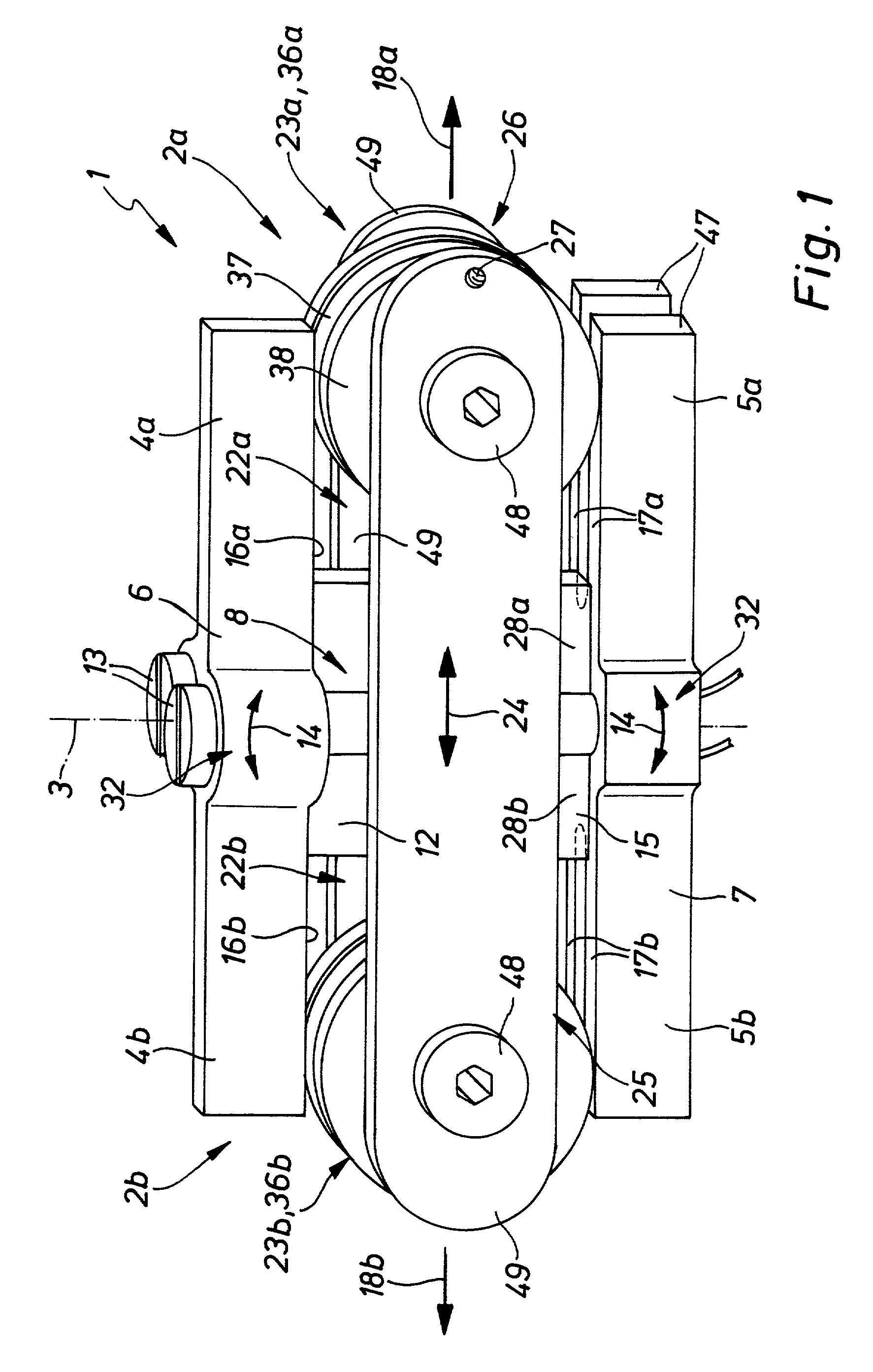
[0026] The drive device 1 illustrated in the drawings comprises two drive units 2a and 2b integrated as a single assembly, which possesses bilateral symmetry with respect to a plane containing a center axis 3.

[0027] Each drive unit 2a and 2b comprises an elongated flexurally stiff and preferably beam-like first pressing body 4a and 4b opposite which at a distance there is a second respective pressing body 5a and 5b. The first pressing bodies 4a and 4b are components of a rigid elongated first pressing element 6, and the second pressing bodies 5a and 5b are joined together as a similar second pressing element 7.

[0028] The two pressing elements 6 and 7 are pivotally mounted in a bearing zone 8 (for pivoting motion in relation to one another) in a plane containing the respective pressing elements 6 and 7. The possible pivotal movements are indicated by double arrows 14. The bearing zone is located adjacent to the center axis 3.

[0029] The two pressing elements 6 and 7 are clamped togeth...


PUM


Abstract

A drive device comprising at least one drive unit having two mutually spaced apart pressing bodies. On the pressing bodies mutual facing pressing faces are provided diverging in a drive direction and having between them a stroke unit engaging the pressing faces of both pressing bodies. Furthermore drive means are present by means of which a drawing together of the pressing bodies may be caused and, as a result of this a displacement of the stroke unit in the drive direction along the pressing faces for the purpose of producing a drive movement able to be externally employed.

Description

[0001] The invention relates to a drive device or transmission, which may for example be employed in the pneumatic equipment sector as a valve drive.THE PRIOR ART[0002] In connection with valves serving for the control of fluid flows in the pneumatic equipment sector so far as a rule valve drives have been utilized, which are constituted by electromagnets or piezoelectric transducers. While being suitable for the transmission of large forces such drives generally only perform a drive movement with relatively small force strokes. Furthermore, there are design limitations as regards presetting the force-stroke characteristic, this restricting the field of application.SHORT SUMMARY OF THE INVENTION[0003] One object of the invention is to create a drive device whose characteristics are able to be varied using comparatively simple means and which in case of need renders possible performing drive movements with a large force and simultaneously a large stroke.[0004] In order to achieve the...

Claims


Application Information

Patent Timeline
Patent Type & Authority Applications(United States)
IPC IPC(8): F16H25/18H01L41/09
CPCF16H25/18H02N2/043Y10T74/18568
Inventor GODEL, MARTINHOFFMANN, MARKUS
Owner FESTO AG & CO KG
Why Eureka
Try Eureka