
Signal processing method for use in an array antenna system in CDMA mobile telecommunications network and recording medium therefor

Inactive Publication Date: 2001-09-13
HANTEL +1
View PDF0 Cites 8 Cited by
  • Summary
  • Abstract
  • Description
  • Claims
  • Application Information

AI Technical Summary

Problems solved by technology

Therefore, even if the power level of the source signal is much higher than that of each of the interference signals, the sum of powers of the interference signals is very high when the number of the interference signals is large so that the communication distortion frequently occurs.
Conventionally, this distortion leads to a serious problem of difficulty in information recovery of the source signal.
However, the methods based on the Eigenvalue Decomposition are not favorable to the mobile telecommunications that requires real time processing because they should processes a plenty of computations, although they provide accurate solutions.
Furthermore, though it seems that another method employing a Least Mean Square Error algorithm has some possibility for overcoming the real time processing since computation load can be reduced to a certain extent as related to the Eigenvalue Decomposition methods, this method has another problem in that a receiver part should know a reference signal.
However, in the conventional nonlinear on-off algorithm, it is difficult to determine the phase gain and change of the output power from the phase gain leads to error when signal environment changes.
Therefore, the conventional nonlinear on-off algorithm is not applicable to the communications because it requires large amount of computations and has difficulty of determining not only adaptive gain .mu. but also the phase gain .DELTA..phi. during phase delay vector computation.
Furthermore, because the phase delay or the weight should be changed continuously when communication environment is time-variant, the real time processing substantially is impossible.

Method used


Image

  • Signal processing method for use in an array antenna system in CDMA mobile telecommunications network and recording medium therefor
  • Signal processing method for use in an array antenna system in CDMA mobile telecommunications network and recording medium therefor
  • Signal processing method for use in an array antenna system in CDMA mobile telecommunications network and recording medium therefor

Examples


Embodiment Construction

[0024] Hereinafter, preferred embodiments of the present invention will be described in detail with reference to the accompanying drawings.

Design of One-Dimensional Optimum Array Antenna

[0025] At first, it will be described in detail for design of a one-dimensional optimum array antenna.

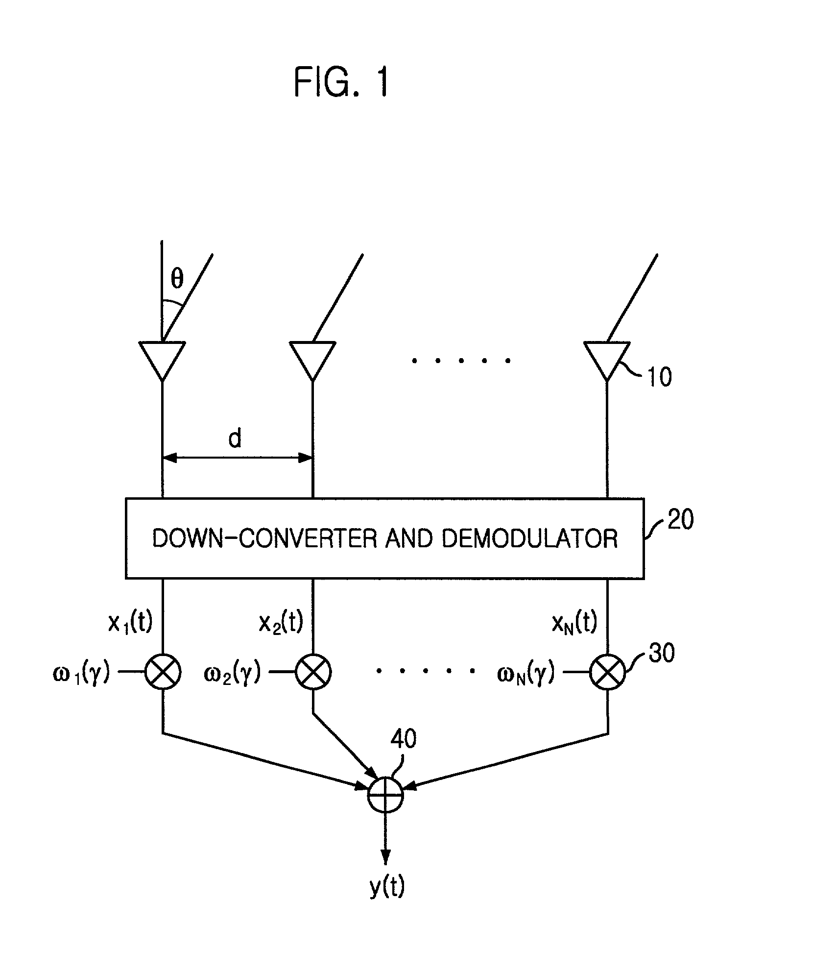
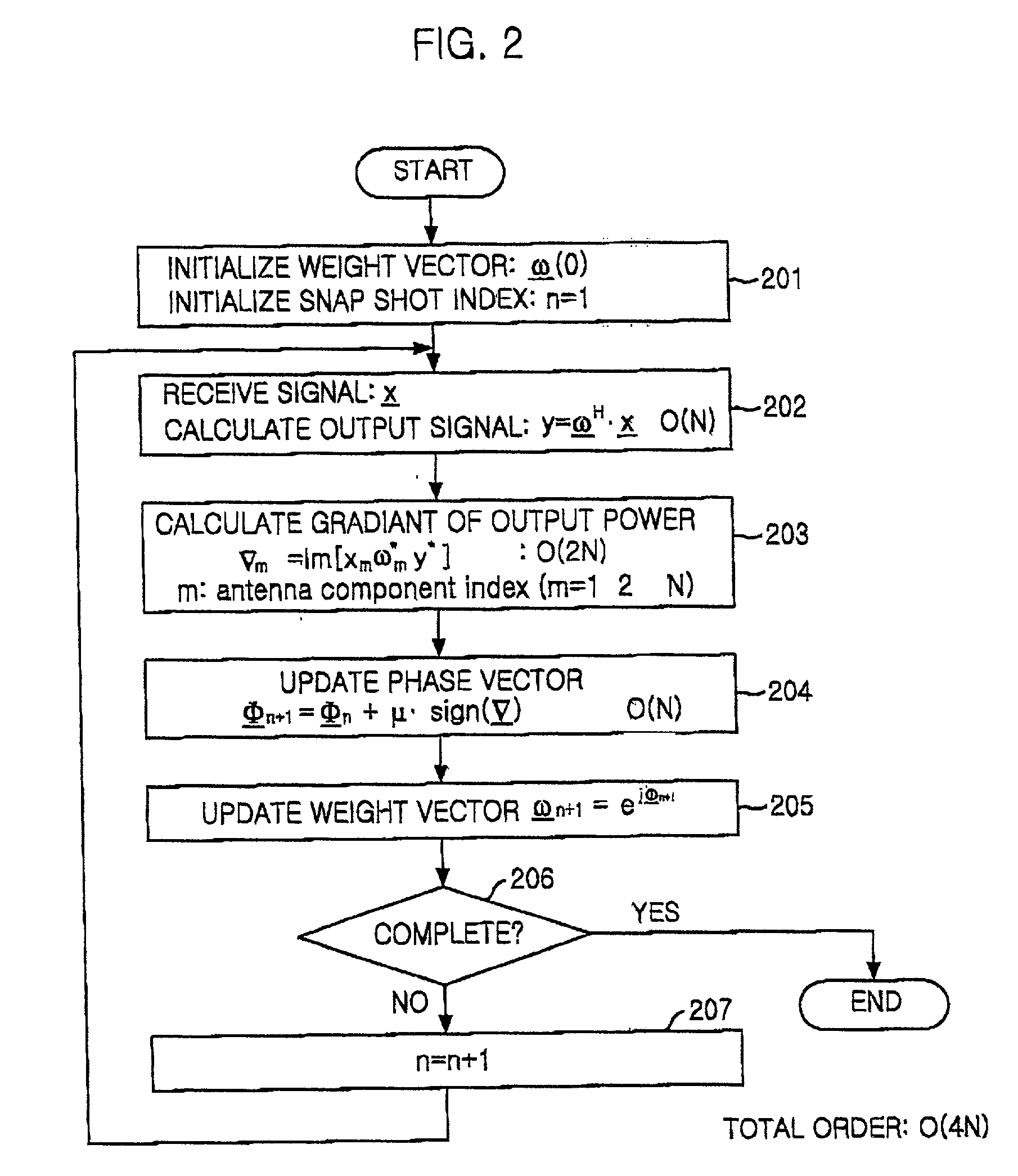
[0026] FIG. 1 is an exemplary diagram of a one-dimensional array antenna system in a CDMA telecommunications network, to which the present invention is applied and FIG. 2 shows a flow chart of a signal processing method for forming an ideal beam pattern in the one-dimensional array antenna system as shown in FIG. 1.

[0027] Referring to FIG. 1, M signals S.sub.1(t), S.sub.2(t), . . . , S.sub.M(t) are applied to N receiving antennas. In FIG. 1, the array antenna includes array antenna elements 10, a down-converter and demodulator 20, a multiplier 30, and an adder 40. x.sub.m(t) is a signal arrived at an m-th antenna, .omega..sub.m, is a complex weight vector applied to the arrived signal at the m-th ant...


PUM


Abstract

The present invention is a signal processing method for use in a CDMA adaptive array antenna system, the method for forming the beam pattern by maximizing a transceiving gain in a direction toward a target mobile station and optimizing the beam pattern in a moving direction depended on a moving direction of each target mobile station during signal transceiving between a base station and the mobile station, the method forming an ideal beam pattern by a simplified computation procedure, and a computer readable recording medium for storing a program for implementing the method. The method comprises determining signature of gradient of output power of the array antenna to the phase of each antenna, updating the phase of each antenna by increasing or decreasing the phase by an adaptive gain depending on the signature of the corresponding gradient, determining weight corresponding to the updated phase, and applying the weight to a signal arrived at each antenna. The present invention increases significantly communication capability per cell and improve communication quality for a given bandwidth.

Description

[0001] The present invention relates to a signal processing method for use in an array antenna system included in a CDMA (Code Division Multiple Access) mobile telecommunications network base station, and, more particularly, to a signal processing method, for use in a CDMA adaptive array antenna system, for forming a beam pattern by maximizing a transceiving gain in a direction toward a target mobile station and maximizing the beam pattern in a moving direction of each target mobile station during signal transceiving between a base station and a mobile station, and a recording medium therefor.PRIOR ART OF THE INVENTION[0002] Generally, in a wireless telecommunications, a source signal and an interference signal are included in a received signal and, more typically, a plurality of the interference signals exist along with the source signal. Communication distortion due to such interference signals depends on ratio of the power of the source signal to sum of powers of other signals. T...

Claims


Application Information

Patent Timeline
IPC IPC(8): H01Q3/34H01Q23/00H04B7/06H04B7/26
CPCH04B7/0617H01Q3/34H01Q23/00H04B7/26
Inventor CHOI, SEUNG-WON
Owner HANTEL
Learn More