Rotary blade of helicopter

Inactive Publication Date: 2001-09-27
SUBARU CORP
View PDF0 Cites 7 Cited by
  • Summary
  • Abstract
  • Description
  • Claims
  • Application Information

AI Technical Summary

Problems solved by technology

However, this tip shape cannot lower the BVI noises.
Therefore, the vortexes generated at the tips of the individual small wings are close to each other and interfere positively with each other and are weakened and diffused.

Method used


Image

  • Rotary blade of helicopter
  • Rotary blade of helicopter
  • Rotary blade of helicopter

Examples


first embodiment

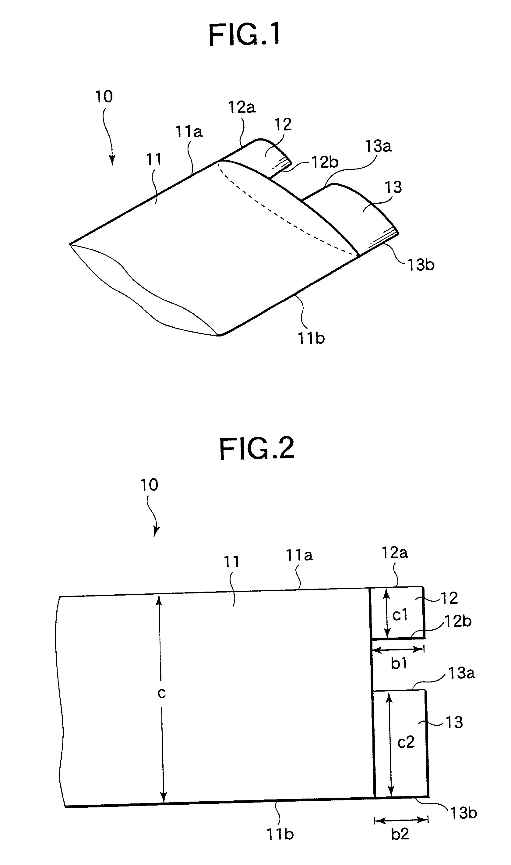
[0054] the invention will be described with reference to FIGS. 1 to 5. FIG. 1 is a perspective view showing the tip of a rotor blade 10 of a helicopter according to this embodiment, and FIG. 2 is a top plan view of FIG. 1. The rotor blade 10, as shown in FIGS. 1 and 2, is attached in plurality to a (not-shown) rotor hub to form a rotor.

[0055] The rotor blade 10 is provided with a base wing 11 having a substantially equal chord length and a rectangular tip shape, and a smaller front wing 12 and a larger rear wing 13 disposed along its chord at the tip of the base wing 11.

[0056] The front wing 12 merges at its leading edge 12a into the leading edge 11a of the base wing 11 and is formed into such a rectangular shape as has a chord length c1 of 20 to 30% of the chord length c of the base wing 11 and a span b1 of 20% to 30% of the chord length c of the base wing 11.

[0057] On the other hand, the rear wing 13 merges at its trailing edge 13b into the trailing edge 11b of the base wing 11 an...

second embodiment

[0074] According to this embodiment thus formed, the base wing 11, the front wing 12 and the rear wing 13 have the tapered shapes. In addition to the effects of the foregoing second embodiment, therefore, the lift distribution at the wing tip is reduced to improve the damping effect of the tip vortex better.

fourth embodiment

[0075] Here will be described the invention with reference to FIG. 9.

[0076] FIGS. 9A and 9B present explanatory diagrams of a rotor blade 10 according to this embodiment. FIG. 9A is a top plan view of the tip of the rotor blade 10 corresponding to FIG. 2 of the foregoing first embodiment, and FIG. 9B is a side elevation of FIG. 9A. Here, this embodiment will be described mainly on different portions by designating the corresponding portions by the common reference numerals to omit their detailed descriptions.

[0077] The rotor blade 10 according to this embodiment Is provided with the base wing 11 having a substantially equal chord length c and formed into a rectangular tip shape. At the tip end of the base wing 11, there are disposed at a spacing of about 20% to 30% of the chord length c of the base wing 11 the front wing 12 having a chord length c1 of 20% to 30% of the chord length c of the base wing 11 and a span b1 of 20% to 30% of the chord length c of the base wing 11, and the r...


PUM


Abstract

A base wing 11, as attached at its root end portion to the rotor head of a rotational drive unit, is provided with a front wing 12 and a rear wing 13 having substantially equal spans. The vortex, as generated at the wing tip, is divided into relatively weak tip vortexes of a front wing vortex 12c generated at the tip of the front wing and a rear wing vortex 13c generated at the tip of the rear wing 13. Since the front wing 12 and the rear wing 13 have equal spans, on the other hand, the front wing vortex 12c and the rear wing vortex 13c are close to each other so that they interact positively with each other and are weakened and diffused. As a result, while the helicopter is hovering, the interactions between the retreating rotor blade of the rotor and the tip vortex generated by the tip of the advancing rotor blade are drastically reduced to suppress the occurrence of the BVI noises.

Description

[0001] 1. Field of the Invention[0002] The present invention relates to a rotor of a helicopter and, more particularly, to a rotor blade of a helicopter for reducing its noises.[0003] 2. Description of the Related Art[0004] Especially when the helicopter is to land, the blade of the rotor interacts with the tip vortex, as generated from the tip of the advancing rotor blade, to generate the BVI noises. It is known that the magnitude of the BVI noises depends upon such a planar shape of the tip of the rotor blade as generates the tip vortex.[0005] A rotor 100 of a helicopter is provided, as shown in FIG. 12, with a plurality of rotor blades 101, each of which has a generally rectangular shape, as its tip is shown in FIG. 13, for example, and which rotate on the center of rotation 102.[0006] Especially when the helicopter is to land, the tip trailing edge vortex 103, as generated at the tip of an advancing rotor blade 101a, does not quickly fall so that a retreating rotor blade 101b in...

Claims


Application Information

Patent Timeline
IPC IPC(8): B64C11/18B64C27/46B64C27/467
CPCB64C27/463
Inventor TSUKAHARA, TAKANORIOBUKATA, MASAHIRO
Owner SUBARU CORP
Why Eureka
Try Eureka