Process and apparatus for mechanically joining metallic components

a technology of mechanical joining and metallic components, which is applied in metal working apparatuses, manufacturing tools, and shape safety devices, etc., can solve the problem that the joining process to be carried out by this apparatus cannot be done in the operation area, and achieve the effect of low profil

Inactive Publication Date: 2001-10-04
HAHN ORTWIN
View PDF0 Cites 5 Cited by
  • Summary
  • Abstract
  • Description
  • Claims
  • Application Information

AI Technical Summary

Benefits of technology

0015] In a beneficial further embodiment of the apparatus of this invention, the impulse-wave conductors coupled to the stamp and die plate are structured as upper and lower tong arms of a shearing-principle support device of the joining apparatus. This embodiment makes possible a quite uncomplicated and low profile construction of the entire apparatus.
0016] Further, it is beneficial

Problems solved by technology

Thus, a rather tall structure results, so that joining processes to be carried out by this apparatus canno

Method used


Image

  • Process and apparatus for mechanically joining metallic components
  • Process and apparatus for mechanically joining metallic components
  • Process and apparatus for mechanically joining metallic components

Examples


Embodiment Construction

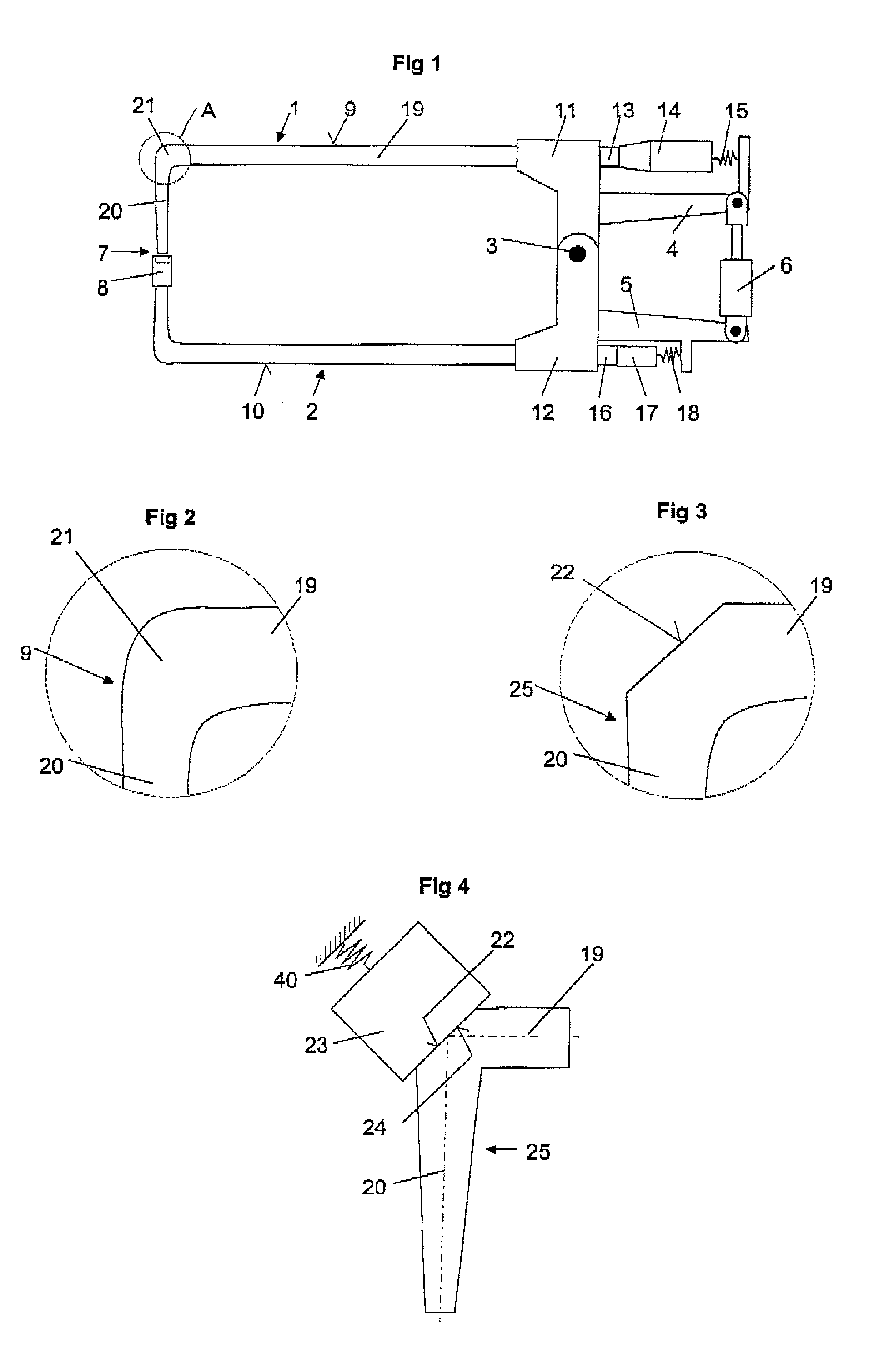
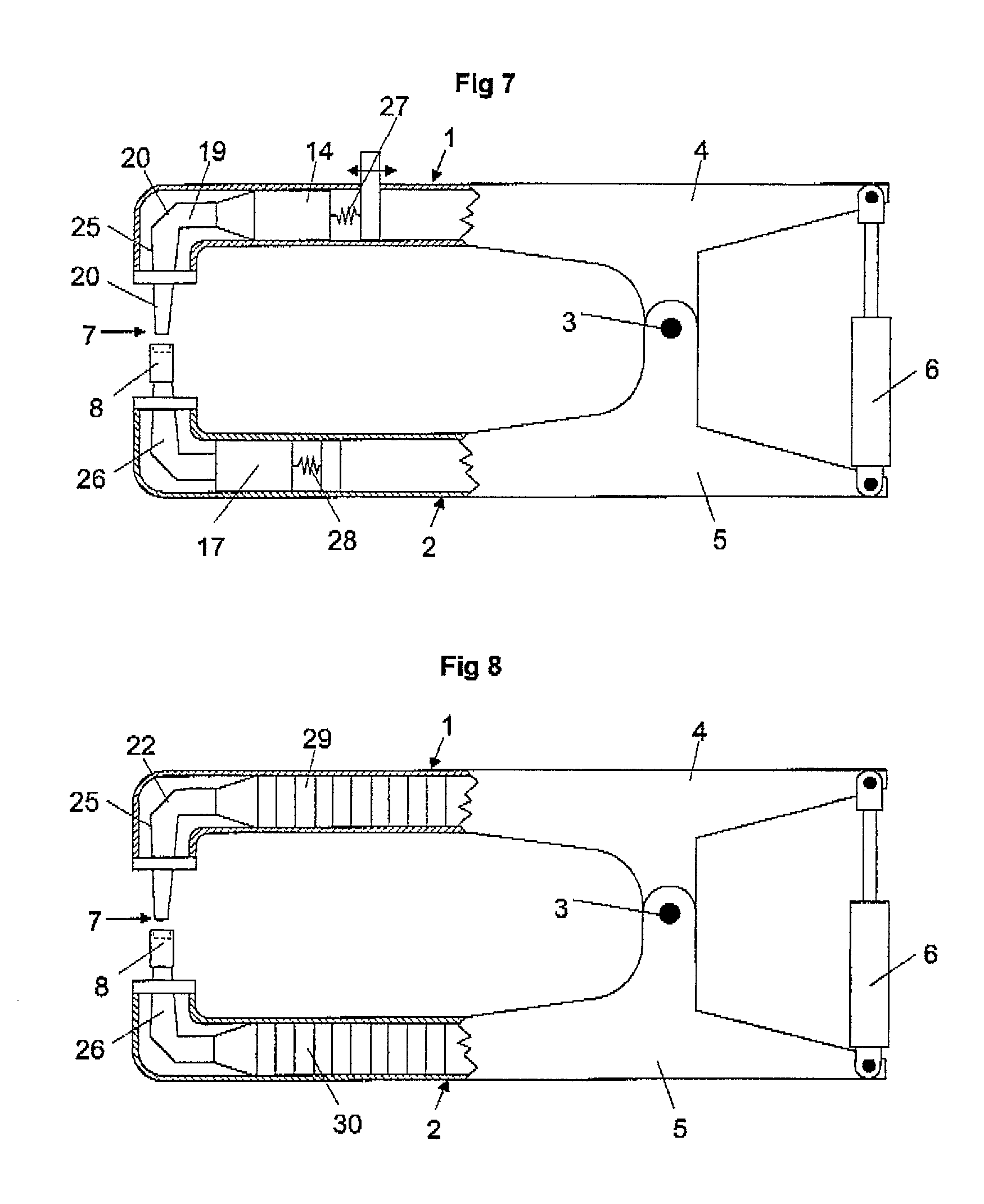
[0026] Each embodiment of a joining apparatus shown in FIGS. 1, 7 and 8 is structured in the manner of shears, with an upper tong arm 1 and a lower tong arm 2 being pivotally coupled to one another at a rotation point 3. End portions 4 and 5 of the upper as well as the lower tong arms 1 and 2 extend beyond the rotation point 3. A motivating unit 6 is arranged between these two end portions 4 and 5 for opening forward tong ends and moving them back together. Such a shearing-tong, with the above described arrangement of the motivating unit, with the motivating unit being arrange behind a center of gravity of the shearing tongs, makes possible a narrow structure for the joining apparatus and improves its maneuverability by having a favorable distribution of its masses.

[0027] In the embodiment of FIG. 1, each of the upper tong arm 1 and the lower tong arm 2 forms a ram, or impulse, wave conductor 9, 10. These impulse-wave conductors 9 and 10 pass rearward through holders 11, 12 that sup...


PUM

PropertyMeasurementUnit
Electrical resistanceaaaaaaaaaa
Metallic bondaaaaaaaaaa

Abstract

A process for mechanically joining plies of thin metallic components lying on one another, and apparatus for its implementation, involves an impulse-wave conductor (9, 25, 31-35) having first and second substantially straight impulse-wave-conductor portions (19, 20, 32, 33) which are arranged at an angle to one another along which impulse waves are transmitted to a stamp (7) to be driven into a component to be joined by impulse force. The impulse waves are redirected between the first and second substantially straight impulse-wave-conductor portions by a structure of an intermediate angled portion (21, 31) located between, the first and second substantially straight impulse-wave-conductor portions.

Description

BACKGROUND OF THE INVENTION[0001] This application claims a foreign priority based on German application 100 10 340.5, filed Mar. 6, 2000, and the contents of that application are incorporated by reference herein.[0002] This invention concerns a process for mechanically joining (for example, clinching and stamping together) two plies of thin metallic components, such as sheet metal, lying on one another, and an apparatus to carry this out, involving a stamp of a joining tool being driven into a component to be joined by impulse force with the impulse force being transmitted to the stamp as impulse waves via an impulse-wave conductor. Examples of such processes and apparatus are disclosed in German patent document DE 197 77 267 C2 and European patent document EP 0 890 397 A1.[0003] In both of these publications a striking tool having an impulse-creating plunger, an impulse-wave conductor and a stamp are arranged in a row along a vertical axis. Thus, a rather tall structure results, s...

Claims


Application Information

Patent Timeline
IPC IPC(8): B21D39/03
CPCB21D39/031B21J15/025B21J15/10B21J15/12
Inventor HAHN, ORTWINSCHULTE, VOLKER
Owner HAHN ORTWIN
Why Eureka
Try Eureka