Thin film head and method for manufacturing the same

Inactive Publication Date: 2001-10-11
PANASONIC CORP
View PDF0 Cites 22 Cited by
  • Summary
  • Abstract
  • Description
  • Claims
  • Application Information

AI Technical Summary

Benefits of technology

0011] The present invention addresses the above described problems and aims to solve them. A hard magnetic layer formed on a free magnetic layer of GMR element is ferromagnetically coupled with said free magnetic layer, and a soft magnetic layer formed to face said hard magnetic layer via a nonmagnetic layer is antiferromagnetically exchange-coupled with said hard magnetic layer. By so doing, the free magnetic

Problems solved by technology

As a result, magnetic coupling between the longitudinal biasing layer and the free magnetic layer of GMR element becomes weak and the direction of magnetization of the free magnetic layer is not orientated in a stable manner, and noise generation increases.
Thus it is difficult for a thin film head of the conventional structure to yield stable reproducing signals.
This leads

Method used


Image

  • Thin film head and method for manufacturing the same
  • Thin film head and method for manufacturing the same
  • Thin film head and method for manufacturing the same

Examples


embodiment 1

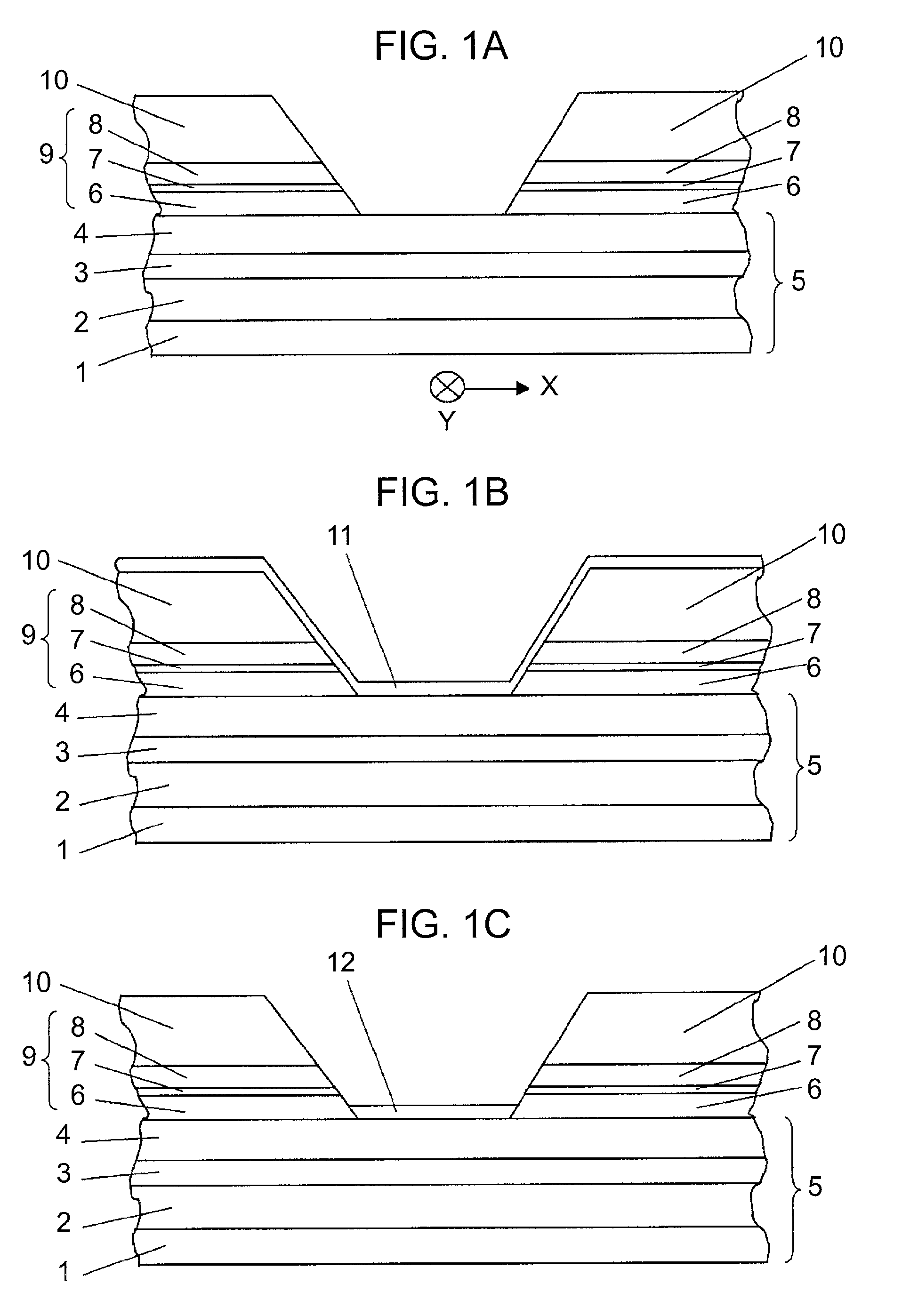
[0032] FIG. 1 shows the structural concept of a thin film head in accordance with embodiment 1 of the present invention; a portion in the vicinity of GMR element as viewed from the sliding surface facing a magnetic recording medium. A lower gap layer (not shown) of Al.sub.2O.sub.3, AlN, SiO.sub.2, or other nonmagnetic insulating material is formed on a lower magnetic shield layer (not shown) formed of a soft magnetic material such as Permalloy, a Co amorphous magnetic layer, an Fe fine grain magnetic layer. On top of the lower gap layer, an antiferromagnetic layer 1 formed of a material such as IrMn, an FeMn alloy, a PtMn alloy, .alpha.Fe.sub.2O.sub.3, NiO; a pinning layer 2 formed of a magnetic material such as a NiFe alloy, Co, a CoFe alloy; a nonmagnetic conductive layer 3 formed of Cu or other nonmagnetic conductive material; and a free magnetic layer 4 formed of the same ferromagnetic material as the pinning layer 2 are deposited sequentially to constitute a GMR element 5.

[0033...

embodiment 2

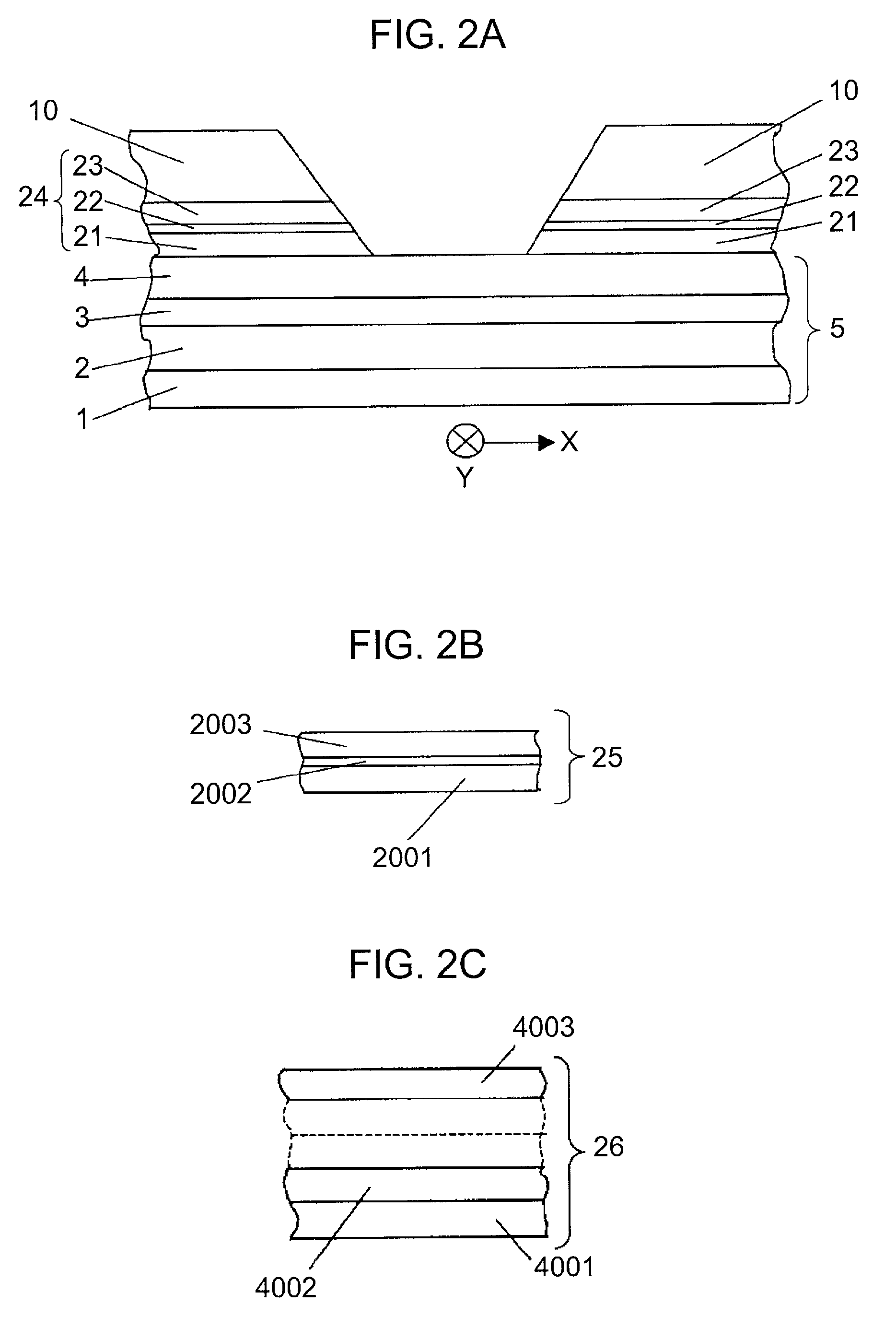
[0058] In the present embodiment 2, where the laminated longitudinal biasing layer is formed of a hard magnetic layer and a soft magnetic layer stacked thereon via a nonmagnetic layer, when the hard magnetic layer is magnetized so that it is provided with a magnetization direction, for example, in the direction of X axis, the hard magnetic layer and the soft magnetic layer are antiferromagnetically exchange-coupled together bringing about quite a stable magnetization direction in the hard magnetic layer. The free magnetic layer of GMR element making physical contact with the hard magnetic layer is ferromagnetically coupled with the hard magnetic layer, and the magnetization direction is orientated in a stable manner to the direction of X axis. Furthermore, the magnetization direction of free magnetic layer in a region free from physical contact with the hard magnetic layer readily assumes the same direction as that of the region making physical contact with the hard magnetic layer. ...


PUM

PropertyMeasurementUnit
Thicknessaaaaaaaaaa
Thicknessaaaaaaaaaa
Corrosion propertiesaaaaaaaaaa

Abstract

A thin film head comprising a GMR element formed of an antiferromagnetic layer, a pinning layer, a nonmagnetic conductive layer and a free magnetic layer; and a pair of the right and the left laminated longitudinal biasing layers, each of the layers containing a hard magnetic layer, a nonmagnetic layer and a soft magnetic layer provided on said free magnetic layer of GMR element. Said hard magnetic layer and said soft magnetic layer are antiferromagnetically exchange-coupled via said nonmagnetic layer, and said hard magnetic layer and said free magnetic layer locating next to said hard magnetic layer are ferromagnetically coupled. The present invention contains also a method for manufacturing the thin film head.

Description

FIELD OF THE INVENTION[0001] The present invention relates to a magnetoresistive thin film head for use in hard disk drives (HDD) or other such magnetic recording apparatus which record signals on magnetic recording media in high density, and reproduce the signals therefrom; more specifically, a magnetoresisitive thin film head in which the free magnetic layer of magnetoresistive element is provided with stable and effective biasing magnetic fields, for yielding signals of reduced noise yet having a high reproducing sensitivity. The present invention relates also to a method for manufacturing the magnetoresistive thin film head.BACKGROUND OF THE INVENTION[0002] The needs for higher processing speed and greater recording capacity are growing among HDDs and other apparatus for recording signals on magnetic recording media. A considerable number of activities are observed for satisfying the needs. For the high density recording, HDDs employ a thin film head; in which an inductive head ...

Claims


Application Information

Patent Timeline
IPC IPC(8): G11B5/31G11B5/39G11B5/40
CPCB82Y10/00B82Y25/00G11B5/3106G11B5/3903G11B5/40Y10T428/1143Y10T29/49043Y10T428/1164Y10T29/49067Y10T29/49044Y10T29/49032G11B2005/3996G11B5/3932G11B5/3163G11B5/3912
Inventor SAKAGUCI, MASAYAFUKAZAWA, TOSHIO
Owner PANASONIC CORP
Why Eureka
Try Eureka